madhippiescientist
New Member
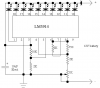
In the spec's for the LM3914 (bar/dot driver), I believe I read somewhere
that I can only have the driver top out about 1.5v below the battery supply
(which is powering the "meter"). Is this true?
I want to integrate the meter, up to 13.5v, in steps of around a 1/3v.
However high up (to 13.8v) I can get, even if it's only 12.3v, I'm going to use
the driver. But I was wondering, what components should I use with the chip
(I don't have the circuit with me, but it's the basic driver circuit and it will be
driving another chip <via dot mode> so I don't really need to worry about a
resistor for the LEDs). So if one was to specify the pins/identification and the
resistor values (i believe it's two resistors) I would need to make the meter
go into this range, I would be GRATEFULL !!
If the chip will only go up to 12.3v (w/ a 13.8v supply and the cutout),
then a step of .25v would be better. Any suggestions gentlemen & ladies???
")