Continue to Site

Welcome to our site!

Electro Tech is an online community (with over 170,000 members) who enjoy talking about and building electronic circuits, projects and gadgets. To participate you need to register. Registration is free. Click here to register now.

  • Welcome to our site! Electro Tech is an online community (with over 170,000 members) who enjoy talking about and building electronic circuits, projects and gadgets. To participate you need to register. Registration is free. Click here to register now.

LM3914 external refrence?

Status
Not open for further replies.

Llamarama

Member
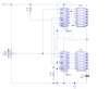
Hello everyone, I'm trying to get a 20 segment driver by chaining a pair of LM3914s as per the datasheet, but i'm having trouble with the voltage reference pins. Is there any way I can manually set a high reference and a low reference (say with a pair of 1k multiturn potentiometers) whilst sticking in a fixed resistor to set the led current/brightness?

I don't know what values of inputs i'll be using yet, but more than likely between 0 and 5v. Also, would it be ok to run this circuit from 9 or 10v? In many of the circuits i've seen online, the supply voltage is at least twice the input voltage.

Any pointers would be greatly appreciated. Many thanks, Mike.
 
Is there any way I can manually set a high reference and a low reference (say with a pair of 1k multiturn potentiometers) whilst sticking in a fixed resistor to set the led current/brightness?
Yes, you can do that. Connect Rhi and Rlo only to your respective refs, connect pin 8 to ground, connect the current-programming resistor between pins 7 and 8. Ok to run from a supply up to 15V.
 
Just note that the LM3914 power dissipation goes up with the supply voltage and the LED current, especially in the Bar mode.
 
Sorry to be a burden once again, I've been breadboarding layouts all night with little success. I can get a 10 segment version to work fine, but the 20 segment version doesn't work past 9 segments.

Once the 1th segment lights, it sticks and no further LEDs light up, this is when I feed it 4.5v.

I have (hopefully) attatched a schematic showing the circuit I'm using, does this look ok?
 

Attachments

  • 20segbargraph.PNG
    20segbargraph.PNG
    31.1 KB · Views: 275
Right, it works fine for bar mode, however when connecting pin 9 of lm3914 1 to pin 1 of lm3913 2, and pin 9 of lm3914 2 to either pin 11 or completely disconnected as is mentioned in the datasheet, I get led 10 lit as soon as the lower scale in exceeded and it stays on. Any ideas as to why this is happening?
 
Here you go...

one shows circuit
one shows DOT graph
one shows BAR graph

eT
 

Attachments

  • LM3914x2-Ckt.png
    LM3914x2-Ckt.png
    111.1 KB · Views: 287
  • LM3914DOT-Sim.png
    LM3914DOT-Sim.png
    48.2 KB · Views: 272
  • LM3914BAR-Sim.png
    LM3914BAR-Sim.png
    47.5 KB · Views: 252
Status
Not open for further replies.

Latest threads

New Articles From Microcontroller Tips

Back
Top