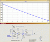
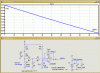
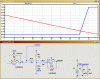
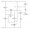
Hi, I am big time beginner with electronics and am trying to build a fuel level indicator for my motorcycle. I found the awesome LM3914 calculator (though not quite sure how to use it yet). I am having a hard time following what schematic it is based on. It looks like this one from the datasheet-

-however, I am not sure how R3 and R4 are connected. To build the gas gauge, I planned on using THIS idea by member on1aag as far as deriving a signal voltage from the tank sender by using the LM317 to provide a constant current. However, there are some things I would like to change. For one, I would like to not reduce the current from the LM317 as much, as it seems to cause it to get quite hot. My power source is around 10-11V and when I built the LM317 side and powered it with a 9V battery, it got very hot. on1aag sets it up to put out only 10mA and create a signal range of 10-1320mV. My fuel sender ranges from around 6 to 80 Ω. What would really help is some explanation of the calculator like a schematic view and maybe an order of operations to make the adjustments. Like, once I have my power voltage, signal voltage range, and desired LED current, what order to adjust the resistor values in the calculator to get it calibrated. Sorry if I am all over the place here. TIA for any help. Please keep it Barney (like the purple dinosaur) simple as I am very new to electronics and all the terms, concepts, and calculations. However, projects like this are teaching me a LOT!
-however, I am not sure how R3 and R4 are connected. To build the gas gauge, I planned on using THIS idea by member on1aag as far as deriving a signal voltage from the tank sender by using the LM317 to provide a constant current. However, there are some things I would like to change. For one, I would like to not reduce the current from the LM317 as much, as it seems to cause it to get quite hot. My power source is around 10-11V and when I built the LM317 side and powered it with a 9V battery, it got very hot. on1aag sets it up to put out only 10mA and create a signal range of 10-1320mV. My fuel sender ranges from around 6 to 80 Ω. What would really help is some explanation of the calculator like a schematic view and maybe an order of operations to make the adjustments. Like, once I have my power voltage, signal voltage range, and desired LED current, what order to adjust the resistor values in the calculator to get it calibrated. Sorry if I am all over the place here. TIA for any help. Please keep it Barney (like the purple dinosaur) simple as I am very new to electronics and all the terms, concepts, and calculations. However, projects like this are teaching me a LOT!