Continue to Site

Welcome to our site!

Electro Tech is an online community (with over 170,000 members) who enjoy talking about and building electronic circuits, projects and gadgets. To participate you need to register. Registration is free. Click here to register now.

  • Welcome to our site! Electro Tech is an online community (with over 170,000 members) who enjoy talking about and building electronic circuits, projects and gadgets. To participate you need to register. Registration is free. Click here to register now.

LM3914 calculator and build questions from an electronics newb

Status
Not open for further replies.
hi goaticus,
Thanks for letting me know that you have finally got it working.:)

Did you have to make any changes to the circuit design.??
 
The only change I made was to the Hero's auxilary LED flasher. I changed R4 to 220K to slow the flash rate down.
 
hi everyone, I have a question about setting the reference OUT of the LM3914. I am using a 5V power for my project and I would like to set the Ref Vout to detect 3.0V at peak level. I used the equation Ref Out V = 1.25(1+ R2/R1), R2=5.1K, R1=3.6K. I expect to see a 3.02V in pin 6&7, however when I measure it, I got 3.32V. Does anyone can help me with this issue??
On page 8 of the LM3914 Datasheet, I saw another equation Vout = Vref*(1+R2/R1) + Iadj*R2. How can I calculate Iadj??? which formula should I use?? the first one or the second one???

hi,
Download and install this calculator.

Woops! corrected link

https://www.electro-tech-online.com/blogs/ericgibbs/126-basic-lm3914-calculator-v3-1.html
 
Last edited:
Thanks ericgibbs, the calculated RefOut value by your calculator is exactly what I expected to see, but in real life, I got 3.32V on the RefOut (pin 7), do you have any idea why?
 
Thanks ericgibbs, the calculated RefOut value by your calculator is exactly what I expected to see, but in real life, I got 3.32V on the RefOut (pin 7), do you have any idea why?

Post a diagram showing your circuit.
 
Here is it, Vin is around 4.8V
 

Attachments

  • lm3914.JPG
    lm3914.JPG
    31.1 KB · Views: 555
Last edited:
hi,
With R1= 3.6K and R2=5.1K it should give a pin7 voltage of 3.02V

If R2 is actually a 5.6K you will get 3.2V, I would check the value of R2.
 
I checked it many times, R2 is 5.1K.

Anyway, do you know how to calculate Iadj from Pin8?

In the LM3914 datasheet page 8, Vout = Vref * (1+R2/R1) + Iadj*R2

Thanks for your help
 
I just checked the current Iadj with a meter, the reading is around 60uA,

Vout = Vref * (1+R2/R1) + Iadj*R2 = 3.02 + (60uA * 5.1K) = 3.32V which matches the measured Vout value, However, does anyone know how to calculate Iadj??
 
I just checked the current Iadj with a meter, the reading is around 60uA,

Vout = Vref * (1+R2/R1) + Iadj*R2 = 3.02 + (60uA * 5.1K) = 3.32V which matches the measured Vout value, However, does anyone know how to calculate Iadj??

hi,
Look at the datasheet REFERENCE graph plot and the Adjust pin current.
It has a range of 75uA to 120uA

If you have 60uA then the second term, Iadj * 5100 = 60uA * 5100 =.306v

and the first term Vref[1+R1/R2] = 1.25 * 2.41 = 3.02V so that gives a Vout of 3.32V which is what you are measuring.

Its important to note that there is wide spread in the parameters of the LM3914.
I would recommend that R2 is a variable resistor, in your project a 10K could be set to give the required Vout/ref
 
Lm3914a.exe

I noticed that Eric posted images of the output from his LM3914a.exe.

I have tried to find this exe on the net but with no luck.

Any chance of anyone (Eric?) posting this exe?

It would be most kind.

Regards
Andrew
 
hi goaticus,
Give me a minute just got my wires crossed at this end...:eek:
I will repost.
EDIT:
Here we go.
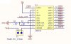
Look at this image, set up the LM3914 this way.

To Calibrate the sensor amp I would use a 100R variable resistor to simulate the tank sensor.
At first set both the Zero and Span pots to 50% rotation.

1. Set the sensor sim resistor to 77R and adjust the Zero so that LED#1 lights.
2. Set the sensor sim resistor to 7R and adjust the Span so that LED#10 lights
repeat this from line number 1 until the LED's are LED#1 for 77R and LED#10 for 7R

OK.
The pic you just show. Is it part of another program or is it a software program on itself. If it is, please give me the link
 
Status
Not open for further replies.

Latest threads

Back
Top