Continue to Site

Welcome to our site!

Electro Tech is an online community (with over 170,000 members) who enjoy talking about and building electronic circuits, projects and gadgets. To participate you need to register. Registration is free. Click here to register now.

  • Welcome to our site! Electro Tech is an online community (with over 170,000 members) who enjoy talking about and building electronic circuits, projects and gadgets. To participate you need to register. Registration is free. Click here to register now.

LM386 Question: What is the purpose of the 1nf capacitor between input and ground (pin 3)?

Status
Not open for further replies.
The OP solution was adding a cap to the emitter, that increases the RF gain, more RF more audio more sound. This goes against your theory that the RF blocked the LM386.
Many AM superhet radios do not have an RF amplifier transistor and they have plenty of sensitivity and volume. Maybe this radio is a (gasp!) super-regen that doesn't even have a detector diode.
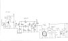
did you not notice that when he added the 1nF capacitor to ground at the input of the LM386 power amplifier then " Using that capacitor gave a large boost in output" which has nothing to do with not having enough RF gain.
 
All AM radios have AGC to avoid overloading with strong local stations. He did not say he is on Mars and trying to receive a very weak signal from Earth.
He said that the output was much more when the RF capacitor was added to the input of the audio amplifier.
Maybe the RF amplifier transistor was oscillating without an emitter bypass capacitor with positive feedback from the RF output of the audio amplifier into its emitter?
 
I was working on my little radio last night and trying to improve the output of the LM386. Two changes I made seem to have had a huge effect on the output volume. The first was to use a small audio transformer between the output (pin 5) and my speaker (not shown in schematic.) I understand why that helped. But, I also found a schematic online that shows a 1 nf capacitor going from pin 3 (input) to ground. Using that capacitor gave a large boost in output as well. Nearly all the other schematics I've seen online do not show this small change, but it sure seems important (at least in my circuit.) So, what does it do and why did it help so much? I understand bypass capacitors in a regular amp prevent degenerative feedback, but this doesn't seem to be the same thing. I've included the schematic.

Hello Stellar,

I have built many LM386 amplifiers and I can assure you that something is wrong in this case.

In a correctly operating LM386, that 1nF capacitor across the input can do nothing but attenuate the input signal at higher frequencies. The 6dB (half voltage) point drop in gain will be affected by the position of the volume control and the source impedance of your detector output. But with the potentometer near the center of its travel, compared to the signal voltage at 1kHz, the voltage into the amp will be half (-6dB) at 66 Khz. At other positions of the potentiometer the half voltage point will be higher, so any attenuation caused by the capacitor will be well above the audio band- as it should be.

It sounds very much like the amp is oscillating, which would not be surprising as there is no high frequency decoupling on the supply line.

To see if this is correct place a 100nf or bigger ceramic capacitor directly across pins 6 and 4 of the LM386. If that does not work add a 10uF upwards aluminum electrolytic capacitor across the same pins in parallel with the 100nF capacitor (positive connection to pin 6). If that does not work you may need to look at the physical layout of the circuit.

The 1nF capacitor is there either as a botch to stop the amp oscillating or more likely to prevent radio signals from entering the amplifier. What can happen is that when AM signals get into the input of an amplifier the protection and parasitic diodes, fabricated into the chip, rectify the AM (detect it) and you get the radio station audio at the output. To do a proper job of the input filtering you should put a 1K resistor between the input potentiometer wiper and the capacitor.

You say that you have connected a 10uF capacitor between the detector and the amplifier. That will almost certainly be an aluminum electrolytic capacitor and will probably be insufficiently biased. There is already a 1uF isolating capacitor in series with the input so just remove the 10uf capacitor and replace it with a link (the existing 1 uF capacitor should be a non electrolytic, solid type).

The other thing you should do is to put a 470uF or larger capacitor across the battery. Can you say what type of battery it is because if it is small or badly discharged that will also cause problems due to the high source impedance. Can you measure the actual battery voltage with a meter while the amp is producing sound?

A final area of concern is the detector circuit on your radio: are you sure you are taking the signal to the amp from across the integrating capacitor in the detector. The other thing is that the detector source impedance may be sufficiently high that the input impedance of the amp is swamping it.

Moving on to the transformer that you have added to increase the volume. I am intrigued by this. Can you give some more details; the impedance of the loudspeaker would be helpful.
 
Last edited:
The OP solution was adding a cap to the emitter, that increases the RF gain, more RF more audio more sound. This goes against the theory that the RF blocked the LM386.

That still doesn't quite explain why the 1n capacitor increased the volume prior to the boost in RF gain due to the bypass capacitor, but it does seem to make my original theory invalid. Back to the drawing board, as they say. Hopefully we can arrive at a better explanation once the full schematic is posted.
 
Gordon, we do not know what is going on really. I didn't want to mention this but it is quite possible that one half of the output stage is blown- Im suspicious of the transformer increasing the volume. A half blown output stage can give surprising results and doesn't sound as bad as you might expect. We do not know what the supply line as seen by the chip is. There is also the unknown of the detector circuit and the output impedance. We really need to see a complete schematic and a pic of the physical side. As I think you demonstrated the LM386 has a lot of gain going up to quite a high frequency so it needs a good layout and decoupling before further investigation.
 
Last edited:
Hello Stellar,

I have built many LM386 amplifiers and I can assure you that something is wrong in this case.

Question #1: The other thing you should do is to put a 470uF or larger capacitor across the battery. Can you say what type of battery it is because if it is small or badly discharged that will also cause problems due to the high source impedance. Can you measure the actual battery voltage with a meter while the amp is producing sound?

Question #2: Moving on to the transformer that you have added to increase the volume. I am intrigued by this. Can you give some more details; the impedance of the loudspeaker would be helpful.

So, I have an oscilloscope now and was able to do some investigating:

In regards to question #1: Using my scope I've determined that the this change: "I found a transistor in my RF amp (the very first stage in my radio) with an emitter going to ground without an emitter bypass capacitor. Apparently the schematic was wrong OR the designer just didn't realize it was a problem. I haven't used the scope yet, but once I put a .047uf capacitor from the emitter to ground the 1nf became irrelevant AND the RF amp is giving me more gain now." - Actually distorted the amplified RF signal coming out of the RF amp. The wave was slightly misshapen and push more toward the positive side of the Y axis. (So the designer was not wrong.) I removed it, and although there was a drop in final output volume the sound quality was better. Interestingly, I did try a 470uf across the battery and that resulted in slightly better volume (not as much as the above change) and improved sound quality. It also eliminated the need for the 10nf previously mentioned, so that had something to do with the problem.

Question #2: Well, the speaker is a standard 8 ohm. It's pretty high quality about 4" in diameter and has a strong magnet in it. Probably much higher quality than most cheap AM radios have. Just changing from a cheesy 2" 8 ohm speaker to this speaker made quite a difference in both volume and sound quality. As to the transformer, pretty basic, it's a 600 ohm to 8 ohm audio transformer, however, I've determined that only using the center tap and not the full input windings is slightly better. Basically, one side of transformer to ground, center tap to the output of the LM386, and then the output wires (red and black) from the transformer to the speaker. This gives a very substantial boost in volume and quality. I'd say it's probably 2 - 3x as loud when using the transformer. Interestingly, this transformer also improves the sound and volume in a high impedance crystal radio earpiece. That indicates to me it may be doing more than just matching impedances. If I can remember, I'll try to scope the output with and without the transformer and see if I can figure anything out.

All AM radios have AGC to avoid overloading with strong local stations. He did not say he is on Mars and trying to receive a very weak signal from Earth.
He said that the output was much more when the RF capacitor was added to the input of the audio amplifier.
Maybe the RF amplifier transistor was oscillating without an emitter bypass capacitor with positive feedback from the RF output of the audio amplifier into its emitter?
Yeah, this simple radio does not have any AGC. When you get a strong station it's LOUD compared to a weaker one.

I've attached the full circuit minus the antenna and one of the tuners (it has an coupling coil with tuner and the tuned main loop.)

Probably the biggest problems with this radio currently is that it has selectivity issues, stations that are closer than about 70 kHz are hard for it to separate and it's not as sensitive as some higher end radios like my Tecsun 880. However, it does pickup every station that would be considered to be in my listening area. The stations the Tecsun can pull in are very weak and long ways away, so the sound quality is quite poor and it only really gets those stations after dark. The super selectivity of Tecsun is very helpful in this regard. With my home made radio those stations would be drowned out by a stronger one in many cases.
 

Attachments

  • FullCircuit.jpg
    FullCircuit.jpg
    833.3 KB · Views: 184
Last edited:
The transformer should reduce the maximum output level. Half of the 600 ohm winding is an impedance of 150 ohms. The datasheet of an LM386 shows that with a 9V supply, its maximum output into 16 ohms or more is about 7.5V peak-to-peak which is 2.65V RMS which produces only 0.047W of power. But without the transformer the 8 ohm speaker gets 6V p-p which is 2.12V RMS which produces 0.56W, a lot more than 0.047W and the transformer loss was not included.

The AM "radio" that has only ONE tuned circuit and has a Jfet (Q1) that is missing a voltage reference of 0V for its gate because a resistor from its gate to ground is missing?
The low value of the output capacitor cuts bass frequencies when the LM386 drives an 8 ohm speaker but it passes bass frequencies when the transformer increases the impedance of the load on the capacitor.

Well, I don't know what to say, it's definitely way louder with the transformer in there. Maybe I'll post a sound clip.

Also, IIFC, I did add a either 10 or 1 meg resistor to the detector Q1 gate to ground (someone else suggested that in another thread), but my diagram doesn't show it (forgot to add it.) It does help slightly with the output. I don't have the actual circuit sitting in front me currently, but I'm pretty sure it's there. Or are you talking about the RF amp Q1? I'll check that tonight and see if adding a resistor there helps if it's missing.

As far as the output capacitor, it original circuit only called for a 10 uf and I upped that to 22o uf which seemed to improve the sound a bit. More than 220 uf doesn't seem to make much of a difference.
 
Since your transformer cuts the output voltage swing then it also cuts the output current and reduces the current from the battery. Maybe your battery cannot supply enough current for the amplifier to produce 1/2W?
Maybe you have a cheap Chinese fake copy of an American LM386? A cheap 9V battery? Did you buy them on ebay?
A simple calculation shows that 10uF feeding an 8 ohm speaker cuts frequencies below 2000Hz, 100uF cuts below 200Hz and 1000uF should be used for audio if the speaker is half decent. The 220uF capacitor is fine feeding the 150 ohms of the transformer but cuts bass sounds when feeding the 8 ohm speaker.

Now, that I'm home I double checked everything. You are correct. I mis-labeled the output capacitor it's a 330 uf not a 220 uf. Also, for some reason, probably a bad connection somewhere, now when I remove the transformer the sound is a bit stronger but more "tinny", so you are right about the "feeding" of the transformer vs. straight through. The sound quality is much better going through the transformer. So, you were right on the transformer thing. Although, I'm still puzzled about why I had the original problem. Also, I do, in fact, have a 10 meg ohm resistor going to the ground from both gates of my MPF102's (detector and RF amp.) Either way, the end result is that I understand what's going on. My next project is going to be trying to improve the selectivity of the radio. I think I will still post a sound clip of the output because this radio really sounds pretty good for such a simple design and the fact that I clobbered it together from various schemetics I found on the web.
 
Last edited:
An AM radio sounds AWFUL because it has a narrow bandpass to avoid interference from other stations that have nearby frequencies. Therefore high audio frequencies are missing. I read that lately AM radio stations have pre-emphasis where they boost audio frequencies around 5kHz that helps make better sound in ordinary radios. But your radio has only one tuned circuit instead of 5 or 6 in an ordinary radio so maybe that makes your radio sound better.
 
Well, if you read the article here: **broken link removed** the author says that a good part of poor AM sound has to do with the detector circuit. The author does allude to your opinion about the bandwidth causing poor sound. My fancy Tecsun 880 allows 9 kHz bandwidth on AM, but you have to set that manually because it's beyond the default. The author says in reality with a good detector this can be fixed on even simpler radios. I used one of his top end detector designs (the last one in the article) and IMO it actually sounds quite good. Of course, one has to keep in mind that it's not stereo. Another improvement I could make is to use a low noise OPAMP. I did have a different one in there that actually sounded better (NTE928M), but it couldn't really drive a speaker and for now, my knowledge doesn't extend to how to take the output from that and into a power amp of some kind. With the output just through a speaker the noise isn't that noticeable, but through headphones it is noticeable. There is substantially more "hiss" with the LM386. I need to learn about to drive a power transistor from the 928 OPAMP (I think.) I don't think it would take much to get it to produce a 1/2 watt or so like the LM386 OR maybe there is a replacement for the LM386 itself that sounds better?

Although this "simple" radio doesn't have all the circuitry of a really modern radio, right now I'm listening to 680 kHz from San Francisco, a station 600 miles from my house. I don't think you'd be able to do that with any FM radio. So, AM MW, it has it's advantages. I do have a pretty good loop antenna though and I plan to improve it in the future by making it bigger. It's probably much better than anything a standard AM radio with a ferrite loop would have though. One thing that I've concluded is that the antenna is THE most important part of a radio if you're trying to listen to anything that's not next door.
 
Last edited:
NTE do not make anything. They buy old parts, store them away for years then erase the original numbers and stamp on their own numbers. They sell them for high prices. An NTE928 is an ordinary lousy old LM358 dual opamp in an old metal case. It is noisy, has audio crossover distortion and has trouble with audio frequencies higher than only 2kHz. There are thousands of audio single, dual and quad opamps that have low noise, very low distortion and a bandwidth of 100kHz or more. Most are available everywhere and are inexpensive.

The radio frequencies of FM stations are 100 times higher than AM stations. Low frequency AM bounces off the ionosphere and curve around Earth but the much higher frequencies of FM stations do not, they go straight and are blocked by the curvature of Earth.
What you recommend for a replacement for the LM386 then? Or do you have a circuit with a better OPAMP that drives a power transistor of some kind? I have some OPAMPs in my parts stash, TL071, OPA227, 741, LM6171, LM353, LM7806. If it can drive a speaker with a transistor or two added I'm willing to try it.
 
Last edited:
What you recommend for a replacement for the LM386 then?
It is fine to drive a speaker to 1/2W if its gain is reduced 10 times (so that its hiss is also reduced 10 times) by removing the capacitor from pin 1 to pin 8.

Or do you have a circuit with a better OPAMP that drives a power transistor of some kind? I have some OPAMPs in my parts stash, TL071, OPA227, 741, LM6171, LM353, LM7806. If it can drive a speaker with a transistor or two added I'm willing to try it.
Your OPA227 would make an excellent preamp to drive the LM386 power amplifier. The 741 opamp has a 47 years old design and is garbage today. The LM7806 is a 6V voltage regulator, not an opamp.
 
Status
Not open for further replies.

New Articles From Microcontroller Tips

Back
Top