Glad I could help. Fair point about the caps, Dr. Pepper. 470nF should be fine as well, or even lower if those aren't available, but I would try not to go lower than about 180nF for C3 and C4.
Also, I think you may be over-thinking Alec's question a bit.

I think his main question (and my question as well) is simple: what is your input device? is it a computer? a phone? a guitar? an Arduino? A bit of context as to what you are using and what you are trying to do with your circuit would be helpful. If something we said is too complex, just ask us to clarify. It's not a bad thing to ask questions, even if they seem basic.
")
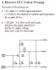
The reason that knowing the input device is important is because different devices will have different output impedance and output signal levels. Something like a guitar pickup has a high output impedance and might not be able to drive a low impedance load like in my schematic. A source with too low a signal level might need more amplifier stages to drive the LM386, and too high a signal level might overdrive the chip at all but low volume.
Let us know how it works if you build it!