arhi
Member
I'm aware that I don't know much about all this .. but this should be as simple as ohm law and it's driving me crazy ...
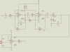
LM358N ..
pin4 (power -): gnd
pin8 (power +): +5V
pin2 (-): +2.32V
pin3 (+): +550mV
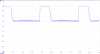
what should be the pin1 (out) ??? from what I know, as + is lower then - .. it should be 0V .. right?? ... well .. it is 4V ?!?!?!?!
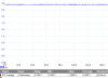
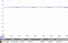
OSC output attached for all three pins ... is there anyone that can shed some light before I give up on this completely
EDIT: no feedback .. pin2 is connected to voltage divider (1 resistor to ground, another resistor to vcc), pin3 is "signal in" and pin3 is connected to osc via resistor
LM358N ..
pin4 (power -): gnd
pin8 (power +): +5V
pin2 (-): +2.32V
pin3 (+): +550mV
what should be the pin1 (out) ??? from what I know, as + is lower then - .. it should be 0V .. right?? ... well .. it is 4V ?!?!?!?!
OSC output attached for all three pins ... is there anyone that can shed some light before I give up on this completely
EDIT: no feedback .. pin2 is connected to voltage divider (1 resistor to ground, another resistor to vcc), pin3 is "signal in" and pin3 is connected to osc via resistor
Attachments
Last edited:


") .. and bloody opamp/comparator should do it ... but looks like my knowledge of basic elco is long gone
.. and bloody opamp/comparator should do it ... but looks like my knowledge of basic elco is long gone