How the -1.25V being generated in crutshows schematic?
With the TL431 sense input connected to its anode, the voltage across it is 2.5V (its minimum voltage)
When the voltage control pot, U3, is at zero resistance then the voltage divider action of R2 and R5 generates -1.25V at the ADJ pin.
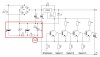
I redrawn the circuit with the transistors.Is my drawing correct?All emitters of the transistors are going to -1.25V point..!
Not quite.
For R1=120Ω in your schematic, then R4 also must be 120Ω going from the transistors emitters to the -2.5V from the TL431.
Also R4 must be changed to 2.5kΩ, 1/2W.
And the base resistors should be more like 3kΩ, not 1kΩ.
But the bigger problem is that the transistors won't completely shut off now with 0V on their inputs because their emitters are going to -1.25V.
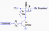
You will need to add another transistor as a level translator such as this:

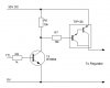
Can I also use a negative voltage regulator to reduce parts count in the red area...
Using a negative regulator instead of the TL431 would eliminate two parts, resistors R4 and R5.
Here's the LTspice simulation of that using an LM337 negative regulator.

")