Continue to Site

Welcome to our site!

Electro Tech is an online community (with over 170,000 members) who enjoy talking about and building electronic circuits, projects and gadgets. To participate you need to register. Registration is free. Click here to register now.

  • Welcome to our site! Electro Tech is an online community (with over 170,000 members) who enjoy talking about and building electronic circuits, projects and gadgets. To participate you need to register. Registration is free. Click here to register now.

LM317 Output

Status
Not open for further replies.
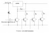
The voltage regulator with an emitter follower at the output has poor voltage regulation because there is no feedback from the output of the emitter follower to the IC's error amplifier.
A 24VAC transformer rated at 3A has a power of 24V x 3A= 72VA. When it is rectified and filtered then the DC voltage is 24V x 1.414= 34V minus one or two high current diode drops (1V each) so its output voltage is 32VDC or 33VDC. The 72VA/33V= 2.18A which is the maximum DC output current, not 3A.
 
Hi Analogkid my transformer is rated 25VA. Its secondary tapping has 0-12AC & 0-12AC.I combined those and made a 24V secondary out.I'm checking without load.
 
The 72VA/33V= 2.18A which is the maximum DC output current, not 3A.
That's actually optimistic.
Due to the high RMS current pulses in a transformer from a rectifier-capacitor supply, the rectified DC output current should be no more than about 60% of the transformer RMS rating, or 1.8Adc for a 3Arms rating.
 
Hi guys.

I changed the LM317 to a more expensive LM350. Now the circuit works well.I can use a 24V transformer(33DC) without no problem.

Hangs on my second question.

Want to shut this down digitally.Making the ADJ pin to ground via a transistor makes output at 1.86V. The regulator wont go for 1.25V minimum voltage :(

I added 1 ohm resistor too to ADJ pin to ground.but hangs on 1.86V.

How to reduce this down?

Here is my final design.
 

Attachments

  • LM350 Mod.JPG
    LM350 Mod.JPG
    44.2 KB · Views: 218
Last edited:
Didn't you read the description and see the datasheet of the ULN2003? It does not have ordinary transistors, instead it has darlingtons with a high saturation voltage drop of the Vbe of its input transistor plus the Vce voltage drop of the output transistor.
The ULN2003 also has series input resistors so your R6 is not needed.
The LM317, LM338 and LM350 are designed to have a minimum output voltage of about 1.25V, plus or minus 0.05V.
 
As AG noted, you need to use regular transistors, not Darlingtons in your circuit to minimize voltage offset if you want to get to 1.25V minimum.
Even better would be small logic-level N-MOSFETs.
 
I will use standard transistors like 2N2222.
That will give a saturation voltage offset of about 30-50mV at the output.
If you want less than that you would need to go to N-MOSFETs.
 
Using the 2N7000 Mosfet to replace a transistor will reduce the output voltage only a little. The minimum output of the LM350 will be a little more than 1.25V.
 
Bad news guys. LM350 Burned out.

I completed my circuit & it worked well with no load. Multimeter showed correct voltages.When it shuts down it also showed 1.25V minimum voltage.

I connected my PCB hand drill which is working from 12V. gave 12V worked nicely.Suddenly I pressed shut down & gave back 12 again.The LM350 burned out.R1 also generates lots of heat....:( Across R1 it shows now 9V :(

I don't know why?Does the back EMF came to LM350? I have never used protection diodes for this design?
 

Attachments

  • LM350 Mod.JPG
    LM350 Mod.JPG
    52.7 KB · Views: 194
hi suraj,
This i a question I asked you days ago, 'do you want 3Amps at the 1.25v shut down'?
If you had said yes, I would have advised that you would exceed the rating of the regulator and it would die.

Eric
 
hi suraj,
This i a question I asked you days ago, 'do you want 3Amps at the 1.25v shut down'?
If you had said yes, I would have advised that you would exceed the rating of the regulator and it would die.

Eric

No Eric I don't want 3A at shut down.I answered that I do not need any current in shutdown condition in post no 6 :)

Shut down is there for this reason.While i'm powering my drill, when I press shut down button the regulator will come to 1.25V & the drill stops working.

I need shut down to stop voltage giving to the equipment's that I use. Equipments are PCB drill, LED Lamps, etc......
 
Last edited:
Bad news guys. LM350 Burned out.

I completed my circuit & it worked well with no load. Multimeter showed correct voltages.When it shuts down it also showed 1.25V minimum voltage.

I connected my PCB hand drill which is working from 12V. gave 12V worked nicely.Suddenly I pressed shut down & gave back 12 again.The LM350 burned out.R1 also generates lots of heat....:( Across R1 it shows now 9V :(

I don't know why?Does the back EMF came to LM350? I have never used protection diodes for this design?
Oh dear, that is a shame.

Using a three terminal regulator is not as simple as it may seem at first.

Here are some precautions it would be advisable to take.
(1) Fit a 1uF minimum decoupling capacitor at the input pin.
(2) Fit a 1uF minimum decoupling capacitor at the output pin.
(3) Fit a 1n400x* diode, cathode to input pin and anode to output pin.
(4) connect a 1n400x diode cathode to output pin, anode to 0V output.

* note x= any number 2 to 7.

Is your regulator mounted on a heatsink. Although the regulator has thermal and current protection it can still suffer thermal shock and other destructive effects.

I know I keep repeating this, but your regulator may be unstable in the frequency domain. It may not be oscillating all the time but only in certain conditions. Oscillations will almost certainly destroy a regulator.

spec

Thanks for being with me. Give me 3-4 hrs time I'll buy a new buddy & will make the changes you pointed out :)

Many thanks.
 
Hi friends.

I did the modifications to the circuit.added protection diodes,added in and out decoupling caps,also changed a new LM350.now the circuit works nice.I also load tested by powering my pcb drill on and off repeatedly and tested.works nicely.no more regulator burns out.

The only downside is when I shutdown the regulator,minimun voltage of 1.25V my PCB drill still rotates :-(

I also added two diodes inseries to the output,but nothing helpful.
 
Do you have a source of negative voltage?
Could you add a half-wave rectifier/filter capacitor and a small neg regulator?
 
Here's a circuit that allows adjustment to 0V for LM317 type regulators.
It uses a capacitor coupled half-wave rectifier and a TL431 reference to generate a stable negative voltage from the transformer AC output.
This allows the voltage at the regulator ADJ pint to go to -1.25V, giving an output to 0V.

upload_2017-3-6_14-11-54.png
 

Attachments

  • LM317 Adj to 0V.asc
    3.1 KB · Views: 173
Last edited:
Status
Not open for further replies.

Latest threads

New Articles From Microcontroller Tips

Back
Top