Continue to Site

Welcome to our site!

Electro Tech is an online community (with over 170,000 members) who enjoy talking about and building electronic circuits, projects and gadgets. To participate you need to register. Registration is free. Click here to register now.

  • Welcome to our site! Electro Tech is an online community (with over 170,000 members) who enjoy talking about and building electronic circuits, projects and gadgets. To participate you need to register. Registration is free. Click here to register now.

LM317 Digital control (DAC)

Status
Not open for further replies.

mhmt.klsogl

New Member
Hi,
I need to control LM317 digitally with DAC. I connected DAC's VCC pin to Arduino's 5 V. SDA pin to A4, SCL pin to A5. Connected A0 and gnd pins to my circuit's gnd which I fed LM317. But, when I create real circuit and test it, I take 2.7 V to 3.3 V from LM317 output. I should take 1.25 to 6.25 V. when I check Arduino's gnd, I realized that it is not 0. ıt is -3 V. Arduino's 5V is actally +2V. which yields voltage different of 5 V. but, I have to connect DAC's gnd to my real circuit gnd which is 0 V. please help me. ı need to take 1.25 V- 6.25 V from output of the LM317. Circuit is attached.
 

Attachments

  • Screenshot (356).png
    Screenshot (356).png
    35.1 KB · Views: 350
Your 100 ohm R should be removed, its causing your LM317 to operate
in constant current mode. Or leave it but your DAC output would have to sink
~ 1.25V / .1K or 12 mA to satisfy the V applied to the 100 ohm R.

Some comments of issues such as minimum load, buffered DAC.....


Regards, Dana.
 
Last edited:
additionally, the porblem is that my arduino has 5v pin with 2 V, and gnd pin with -3 V. overall 5v pin gives 5 volts which is okey. but, ı have to connect my dac vdd pin to arduino's 5 v pin (2 V), and gnd pin of dac to my circuit's gnd (0 V). which yields 2- 0 = 2 V, and this causes my output of LM317 differently.
I set output of LM317 to 1.25 V without DAC, just connecting adj pin to gnd. but when ı connect dac (set to 0 v which act like gnd) to adj pin, the LM317 output gives 2.5 V instead of 1.25 V. ın this situation, dac's gnd is connected to actual 0 V (circuit's gnd).
 
also, in addition, my aim is to drive laser diode with digitally controlled LM317. so, ı need to take low voltage reference as 0 V which is my circuit's gnd, not arduinos -3 V gnd.
 
The Arduino cannot have a -3V GND unless your grounds are not tied together. Same for the Arduino +5V, it is +5V compared to the Arduino GND. DAC ground must be same as Arduino GND. Reading different voltages means you are not referencing the same ground. That will also make everything else not work right....
Tie your grounds together....
 
1. what should I place in the place of 100 res?
2. ı need to add buffer btw the output of dac and adj pin of LM317. Am I rigth?
1) My error, keep 100 ohms, its used to insure min load of 10 mA is met to keep LM317 in regulation.
Its value should be Vomin / Iomin = 1.2V / .01 = 120 ohms.

But I would connect it from output to ground, that way no need for buffer from DAC as the ref
pin current is a max of 100 uA. So your DAC must be able to sink 100 uA in order to drop the
LM317 to its min output V of 1.3V. Your DAC can handle this ref pin current, eg. it is buffered
by internal OpAmp.

In order to drive output to 0V of LM317 you need to swing its ref pin below ground. By its
nominal 1.25 Vref value. To do this you could use a R divider, relatively low values in K ohms,
one end to DAC, the other end to - 1.25 or more negative, a stable regulated V, and the
common junction to the LM317 Vref pin. And in your code take into account the offset
needed to gen 0V out of LM317.

Regards, Dana.
 
Last edited:
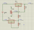
Here is a rough sim of the design

1669152581627.png


I do not have the correct values for R2 R3 divider set, you can calc that on your own.


Regards, Dana.
 
No, that drives the LM317 adj pin with a V source so Vdac becomes
irrelevant. You could scale this with an OpAmp between DAC and ADJ
pin if you have a negative supply for the OpAmp :

Note in this case Vref is +, but you need a - supply for the OpAmp.
OpAmp must be RRIO.


1669202758072.png


You basically want Vadj to range from -1.25 to 6.25 to get LM317
to range its Vout from 0 to + 5, eg Vdac must output

Vout317 = Vdesired - 1.25

Or just use the circuit I posted in post #8


Regards, Dana.
 

Attachments

  • 1669202218385.png
    1669202218385.png
    148.5 KB · Views: 207
Last edited:
Fırst of all, I am gratefull to all your help. I tried your answer which was about connecting -1.25 V. But when I connect, it did not work. LM317 becames to give nonsensical voltage. For example, when I did not connect -1.25V, it gives 6.25. after I connect -1.25, it gives nearly 2.3 volt. Why? My connection is attached. MCP4725 (DAC) is supplied by Arduino. All grounds are common.
 

Attachments

  • Screenshot 2022-11-25 155027.png
    Screenshot 2022-11-25 155027.png
    55.4 KB · Views: 189
Almost forgot. Because of the minimum load requirement when DAC is at 0,
and Vref therefore at -1.25 per my schematic, the min load of 12 mA has
to exist on the LM317 to stay in regulation. So thats an R of 1.25 / .012
= ~ 100 ohms, tied from output pin to - 1.25 V. My schematic tied it to
ground but it should be tied to - 1.25 so that when LM317 Vout = 0
there is a 12 mA load on the LM317.


Regards, Dana.
 
should I connect a resistor to the output pin of the DAC?
Or could I connect a 1.25 V zener diode to the output of the LM317? Is this fix it? If yes, which would be better.

Per schematic this is connections for Vref of LM317 :

1669391449206.png


The R2, R3 values approximate, you need to calc them to give you
0V Vout when Vdac is 0, and Vdac = 5 V for Vout = 5V.
I only approximated them.

Vdac____Vref____Vout
__0_____-1.25_____0
_+5_____+3.75__+5

When you do your calcs it may be that the Vrefneg must be larger,
say -2.5V, in order to get the equations satisified. Thats becuse if Vdac
= 0V there is a V divider R2, R3 not allowing the full -1.25V to the
LM317 ref pin. You can see in sim its not going all the way to Vout = 0
when Vdac = 0. Becuse the -1.25 Vref is being attenuated by the divider.

Just work all that out with simple Kirchhoff law of the Vref pin circuit.

Again the Vref pin must range from -1.25V to 3.75V for Vout going
from 0V to 5V.

Notice the polarity on the 1.25 V source its - (NEGATIVE) 1.25V

Notice I also changed R1 to connect to the -1.25V.


Regards, Dana.
 
Last edited:
A zener ref would look like this -

1669392462161.png


You have to calc R4 to produce min Vz current.

Note there are reference diodes that are more precise than a zener,
available in 1.2, 2.5, and other voltages. ON Semi, TI, Analog Devices,
ST make them.


Regards, Dana.
 
Last edited:
I have another question.
Can I get -1.25 V from main power supply (which fed LM317) with voltage divider. Or can I get it from Arduino?
Note: I have to connect whole circuit to same gnd.
 
What is your power source ? USB ?

You will have to use switch mode inverter or a osc that can be rectified
to produce qa neg voltage, and then a zener or reference diode to get
value. I recommend going for 2.5 V ref diode (instead of 1.25, eg. prior
discussion) so you need a 5V or so source to run an osc that you can rectify.

Or use Arduino PWM output to get an osc, and then something like this
to get negative V.

1669408068606.png


Then
1669408405915.png


or
1669408439936.png


Or an inverter or switch cap .....


Just google, lots of approaches.


Regards, Dana.
 
Last edited:
Hi again,

I am very very very gratefull to you first of all.
I have another situation.
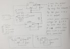
I have designed something that supply 0 to 5 volt by using LM317 and LM337. Details are given in attached files.
My question is:
When I built this circuit on Porteus, it works very well. Proteus ss is attached. But when I create this in real life, it does not work. Why? Where and what is the problem/s?
I must supply everything with one 9 V battery or adaptor. How should I connect all grounds including Arduino's ground?
After getting 0 to 5 V, I am gonig to connect 3 diodes and a 8.2 ohm resistor at the output. I need 250 mA through this circuit (3 diodes and a 8.2 ohm resistor) when output of LM317 is 5 V. Where can I connect this circuint's (3 diodes and a 8.2 ohm resistor) gnd?

Thanks in advance.
Note: The potanitometer in Proteus represents output of DAC.
 

Attachments

  • Screenshot 2022-11-29 180230.png
    Screenshot 2022-11-29 180230.png
    28.2 KB · Views: 195
  • Screenshot 2022-11-29 180253.png
    Screenshot 2022-11-29 180253.png
    27.8 KB · Views: 193
  • 1669735243582.png
    1669735243582.png
    52.7 KB · Views: 179
  • 20221129_180356.jpg
    20221129_180356.jpg
    1.1 MB · Views: 205
Status
Not open for further replies.

Latest threads

New Articles From Microcontroller Tips

Back
Top