Continue to Site

Welcome to our site!

Electro Tech is an online community (with over 170,000 members) who enjoy talking about and building electronic circuits, projects and gadgets. To participate you need to register. Registration is free. Click here to register now.

  • Welcome to our site! Electro Tech is an online community (with over 170,000 members) who enjoy talking about and building electronic circuits, projects and gadgets. To participate you need to register. Registration is free. Click here to register now.

LM317 - Adjustable output linear regulator, Amp & Volt incorporation

Status
Not open for further replies.

Simon822

Member
Hello,

"Huston we have difficulties". (I know what some would think: "Sir, your problem does not constitute an emergency our part". And you're right. Thank you very little!!!)

Onward...

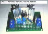
Have put together an adjustable output linear regulator utilizing LM317. My knowledge of electronics is very limited.
http://www.learningaboutelectronics.com/Articles/LM317-voltage-regulator

Details:
Supply is 24Volts - DC.
- LM317T
- (2) adjustable trim pots
- Output: 0.015 mA.

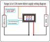
Difficulty arises when attempting to incorporate, Amp & Volt meters, on the output.

Schematic posted on vendors site, not working.

Meter:
http://www.amazon.com/gp/product/B079HV6TLW/ref=ppx_yo_dt_b_asin_title_o04_s00?ie=UTF8&psc=1

Could use some advice.

Best regards, and
Ameter+Voltmeter - wiring 01.png

Thanks
 

Attachments

  • ! - LM317+R1=502+R2=101.jpg
    ! - LM317+R1=502+R2=101.jpg
    391.6 KB · Views: 127
  • 1 - 512EWxJxC7L.jpg.jpeg
    1 - 512EWxJxC7L.jpg.jpeg
    69.6 KB · Views: 134
  • 2 - 51t4dqPfqfL.jpg.jpeg
    2 - 51t4dqPfqfL.jpg.jpeg
    49.6 KB · Views: 121
So, what part of the system is not working?

What part of it is working? Or is it all completely dead?
 
118669


This is what you have set up. If you connect a 6 V or 9 V Battery to the power supply and No load, does the Display show the voltage? If not, your display is faulty.
 
ChrisP58 and Ramussons, thank you for reply.

Here's what happened:

Have installed Amp &Volt meter as the scheme calls for,
on screen Volts are posted OK, however Amps show "0".

Now, testing output, (which is most important factor),
to see if I have 0.015mA's. Then screen goes - blank!!!

So, I must be doing something "right"?

'Cause then the question arises; how do I find out, output -
mA's - once the meter is installed?

Thank you kindly
 
Last edited:
Nothing in the circuit draws only 0.015mA which is 15 millionths of 1A.
The schematic of the LM317 shows only ONE trimpot for adjusting its output voltage, not two trimpots. Why do you have two trimpots?
Your circuit has no load so of course the meter will show ZERO current.

R1 in the circuit should NEVER be a trimpot.
The LM317 circuit you posted is wrong anyway. The datasheet shows a 240 ohms resistor for R1 that is shown with an LM117 more expensive IC. The less expensive LM317 uses 120 ohms for R1 and a lower value for R2 than the 720 ohms for an LM117.
 
Ah, Audioguru, Hello, and thank you for your reply.
I like your posts, and I'm pretty sure you have a multitude of followers that consider your help as; "on top of the list"and very appreciative.

Curently, awaiting on new parts to arrive, to put together - another similar system. I apologize for my shortcomings in the electronic branch, and my knowledge in this field is limited. I will put an effort to place a schematic of intended system, so folks here can have a better understanding of my intention, and difficulties, in achieving intended result, (parts should be here by next week, I'm hopping!).

Mean time, thank you all, and I'm wishing you a pleasant week-end.

Regards

Simon822
 
There is nothing in that circuit that draws only 15uA. The operating current of the LM317 is typically 50uA to 100uA max. The current in R1 and R2 is supposed to be 10mA when there is no load.
 
Hello, Audioguru, and thank you for your reply.

- First, I'm awaiting on new parts to redo my intended gadget, from fear that something might have burnt up, and yes I'm working on a exact schematic to place a visual, here, for correct identification/intention.

Why do you have two trim-pots?

- Two, adjustable trim-pots are for fine-tuning. The ground of both pots are not connected, (wiper of first pot supplies the second pot, where further fine tuning is possible). Without fine tuning to 0.015mA's, this system would be useless.

- In the back of the Amp & Volt meters, there are two coresponding adjustments. One for volts and one for amps, (which was not modified.)
118713

- The thing is, when purchasing these gadgets on line, it is impossible to locate company of origin to call, email, ask for help! When inquiries made they inform to contact manufacturer!

Thank you so much.

Regards

Simon822
 
You do not need a fine tuning trimmer resistor because the main one needs 10 turns to go from one to the other end.
I do not see the 240 ohms resistor on your LM317 circuit. With the 5k trimmer the output voltage will try to be adjusted to +27.3V (impossible with your 24V supply) so most of its adjustment range is wasted and +5V will be difficult to set.

The meter you bought from Amazon is cheap Chinese junk with no-name-brand. It might or might not work properly. If it was made with good accuracy then it would not have the calibration trimpots for you to fiddle with. My name-brand DMM has extremely good accuracy and it has no trimpots to fiddle with.
 
Hello, Audioguru, and thank you for your reply.

As soon as parts arrive, will put together a system as you suggested.
Question; would there be a "online" calculator to see what other parts I have left to compose the new one/system?

Thank, very much.
Please, have a safe week-end.

Regards

Simon822
 
Question; would there be a "online" calculator to see what other parts I have left to compose the new one/system?
An LM317 is extremely simple. I guess you do not have its datasheet.
It needs only two resistors to set its output voltage: a 120 ohms resistor R1 (some articles wrongly say the 240 ohms used for the more expensive LM117) and a potentiometer R2 that has its maximum resistance calculated with the maximum output voltage you want, Ohm's Law and simple arithmatic.

You do not set the output current, Ohm's Law and the load resistance does that.
 
Here is the datasheet for the LM317 https://www.ti.com/lit/ds/symlink/lm317.pdf Read and understand it. If you have questions, please ask.

A search for "lm317 calculator" will bring up lots of choices. Double check what the calculator gives you against the equation and guidelines in the datasheet. More than once I've seen online calculators be wrong, or give values that are accurate, but violate the chip manufacturers recommendations.
 
Status
Not open for further replies.

Latest threads

Back
Top