Continue to Site

Welcome to our site!

Electro Tech is an online community (with over 170,000 members) who enjoy talking about and building electronic circuits, projects and gadgets. To participate you need to register. Registration is free. Click here to register now.

  • Welcome to our site! Electro Tech is an online community (with over 170,000 members) who enjoy talking about and building electronic circuits, projects and gadgets. To participate you need to register. Registration is free. Click here to register now.

LM2671 - adding an LED to circuit

Status
Not open for further replies.

mihirshah100

New Member
Hello

I want to use a "LM2671" as part of my project to output a 5v so I can charge a mobile phone using a USB cable. The voltage input will be around 12V.

The data sheet for the component LM2671 is:
https://www.farnell.com/datasheets/1640746.pdf

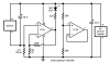
I have attached a picture to show the circuit I will be using:
1.jpg

My problem is I would now like to attach an LED to this circuit so I know when the phone has finished charging. Does anyone know how I will be able to do this please?

Thank you in advance
 
You did not build a charger. Instead you built a switched-mode 5V power supply that feeds the charging circuit that is inside the phone. The charging circuit might be able to light an LED when it finishes charging.

Build a circuit to amplify the voltage across an added low value (maybe 3.3 ohms?) current-sensing resistor. When the current stops then it lights an LED.

Thank you for your reply

Can i not just add a USB female connection to it at the output:
USB_TypeA_01.jpg
The USB can then connect to this from the phone so it can charge.
 
Your 5 volt power supply doesn't know when the battery is charged. The charger knows that.
Bur as AG said the current drawn from the supply will be very low when the battery is full. This could be detected if you want to add some stuff.
 
Your 5 volt power supply doesn't know when the battery is charged. The charger knows that.
Bur as AG said the current drawn from the supply will be very low when the battery is full. This could be detected if you want to add some stuff.

Ohh ok
Thats the part i kind of need help with.
Do you know what type of design i would need to add to detect that please?
 
Do you know what type of design i would need to add to detect that please?
I told you in my last post. Here are some details:
1) Add a low value resistor in series with the 5V power supply feed to the phone. If it is in the negative (ground) wire then an opamp in an LM358 can amplify the voltage caused by current in the resistor. The charging circuit will reduce the current then stop the current when the battery is fully charged.
2) The opamp can feed a transistor that turns on when the current is stopped.
3) The transistor turns on an LED to indicate that the battery in the phone is fully charged.

Thank you
Would something like this work?
2013-02-14 20.37.59.jpg

Thank you
 
1) You have the 5V power supply connected to the input of the opamp instead of powering it.
2) You have the output of the opamp connected to the phone but its output cannot supply enough current to power the charging circuit.
3) You have the LED in series with the very high resistance input of the opamp so it will never light.

I used a 3.3 ohm resistor as a current sensor for the charging current to the phone.
I used the first opamp as an amplifier with a gain of 101 times. Then when the charging current is more than 10mA the output of this opamp is high which turns off the LED. When the charging current is less than 10mA then the output of the opamp goes low which lights the LED.
I disabled the second opamp.

An LM358 dual opamp is used because it is available almost eveywhere and has inputs that work at a voltage as low as ground.
 

Attachments

  • opamp current sensor.png
    opamp current sensor.png
    17.5 KB · Views: 146
1) You have the 5V power supply connected to the input of the opamp instead of powering it.
2) You have the output of the opamp connected to the phone but its output cannot supply enough current to power the charging circuit.
3) You have the LED in series with the very high resistance input of the opamp so it will never light.

I used a 3.3 ohm resistor as a current sensor for the charging current to the phone.
I used the first opamp as an amplifier with a gain of 101 times. Then when the charging current is more than 10mA the output of this opamp is high which turns off the LED. When the charging current is less than 10mA then the output of the opamp goes low which lights the LED.
I disabled the second opamp.

An LM358 dual opamp is used because it is available almost eveywhere and has inputs that work at a voltage as low as ground.

Thank you very much for your help.
So if I was to connect the circuit like this, would it work how I want it to?
Final1.png

Thank you
 
So if I was to connect the circuit like this, would it work how I want it to?
No.
Your circuit will not work because the current used by the charging circuit in the phone does not flow through the 3.3 ohm current-sensing resistor.
Then the output of the opamp will always light the LED.
It should be like my last schematic like this:
 

Attachments

  • opamp current sensor again.jpg
    opamp current sensor again.jpg
    211.6 KB · Views: 142
No.
Your circuit will not work because the current used by the charging circuit in the phone does not flow through the 3.3 ohm current-sensing resistor.
Then the output of the opamp will always light the LED.
It should be like my last schematic like this:

Thank you
I will try and simulate it as soon as I can on ISIS.
 
Your SIM program might not have an accurate model of the LM358 dual opamp.
Why simulate it? Instead, make the simple circuit and test it.
 
Status
Not open for further replies.

Latest threads

New Articles From Microcontroller Tips

Back
Top