Okies here's the deal I have a circuit I charger based on the LM317T as the pcb's are layed out I have two or three in a box, optimally at peak the circuit will drain 450+ from the supply which will then reduce as the charge completes.
right now I'm using the difference between 12 and 5V from a psu to power the circuit at least on 5 of the 9 chargers I have built the other 4 are paired in twos which are powered by motorola 8.4V adapters where the current is only limited by the supply which is 750 mA rated. Which means at peak times it drains the full 750 and maybe a bit more but not much.
Of course I could slap the circuits on 12V but that would cause heat problems since the packages I choose for the chargers don't have that great of a ventilation also 8.4V is a bit much the lm317T needs a 3V differential to work properly the charging voltage is 3.65V and the current limiting resistor is 1ohm which causes a voltage drop. total voltage I need is around 7.2 to 8V the optimal will have to be determined by experimentation.
now the power supply will only supply 7V 12V and 5V I'm pretty much stuck either slow charging or using some sort of voltage regulator. Now the cases I'm using are surplus samsung handsfree kits with several voltage regulators inside the high current one is the one amp LM2575-adj. the thing is that the chargers are linked in the cases in matches of three so I would need about 1.35A to supply those at whatever voltage.
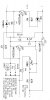
I don't want to waste more electricity then I have to and redesigning the charger is not really an option. So my third option is slaughter the parts from several of the handsfree board (not a problem soldering wise). and build several variable voltage regulators but the catch is the sets of three will always be under powered. Unless I could join the output of several of these lm2575 circuits in parallel. the question is is that doable or will it fry the circuit. second question if I do that should I choose a bigger output cap on each circuit Like a 1000uF cap in order to filter the supplies from each other. and if I look at that adjustable circuit in the pdf should I use two resistors and a 1K pot to get a finer resolution if I look at the max ratings it seems like I might be able to get away with a 1.35A current if I heatsink the thing. Also the 12v to 7.2 or 8V is not as great a jump as going from 40V which should be more work what do you guys think?
terramir
right now I'm using the difference between 12 and 5V from a psu to power the circuit at least on 5 of the 9 chargers I have built the other 4 are paired in twos which are powered by motorola 8.4V adapters where the current is only limited by the supply which is 750 mA rated. Which means at peak times it drains the full 750 and maybe a bit more but not much.
Of course I could slap the circuits on 12V but that would cause heat problems since the packages I choose for the chargers don't have that great of a ventilation also 8.4V is a bit much the lm317T needs a 3V differential to work properly the charging voltage is 3.65V and the current limiting resistor is 1ohm which causes a voltage drop. total voltage I need is around 7.2 to 8V the optimal will have to be determined by experimentation.
now the power supply will only supply 7V 12V and 5V I'm pretty much stuck either slow charging or using some sort of voltage regulator. Now the cases I'm using are surplus samsung handsfree kits with several voltage regulators inside the high current one is the one amp LM2575-adj. the thing is that the chargers are linked in the cases in matches of three so I would need about 1.35A to supply those at whatever voltage.
I don't want to waste more electricity then I have to and redesigning the charger is not really an option. So my third option is slaughter the parts from several of the handsfree board (not a problem soldering wise). and build several variable voltage regulators but the catch is the sets of three will always be under powered. Unless I could join the output of several of these lm2575 circuits in parallel. the question is is that doable or will it fry the circuit. second question if I do that should I choose a bigger output cap on each circuit Like a 1000uF cap in order to filter the supplies from each other. and if I look at that adjustable circuit in the pdf should I use two resistors and a 1K pot to get a finer resolution if I look at the max ratings it seems like I might be able to get away with a 1.35A current if I heatsink the thing. Also the 12v to 7.2 or 8V is not as great a jump as going from 40V which should be more work what do you guys think?
terramir