Gregory
Member
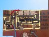
I have Built a basic 12 V DC circuit using a LM317T regulator but I can not get the voltage to adjust Using 500K pot.
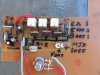
If I apply 5 Volts to the circuit Pin 2 and 3 are the same Voltage when adjusting the POT but pin 1 has the veriable voltage.
The veriable voltage should be pin 2 Where Hav I gon wrong.
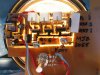
I will post a circuit of thge Voltage regutator.
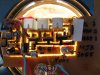
If I apply 5 Volts to the circuit Pin 2 and 3 are the same Voltage when adjusting the POT but pin 1 has the veriable voltage.
The veriable voltage should be pin 2 Where Hav I gon wrong.
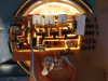
I will post a circuit of thge Voltage regutator.
")
