Continue to Site

Welcome to our site!

Electro Tech is an online community (with over 170,000 members) who enjoy talking about and building electronic circuits, projects and gadgets. To participate you need to register. Registration is free. Click here to register now.

  • Welcome to our site! Electro Tech is an online community (with over 170,000 members) who enjoy talking about and building electronic circuits, projects and gadgets. To participate you need to register. Registration is free. Click here to register now.

little transmitter

Status
Not open for further replies.

BC548C

New Member
Hi,

I'm new here and I hope I'm in the right forum.
In the past two weeks I've built some FM transmitter circuits. My aim is to create very simple circuits.
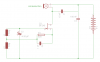
The schematics are shown in the attachment.
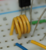
The coil in the first schematic ist made of jumper wire. Its diameter is about 5 mm, the length is about 7 mm and it has got 4 turns. In the second schematic aren't actually two coils, it's one coil with a tap (I didn't know how to draw this in my schematic porgram). Diameter 5 mm, length 7 mm and 4 turns. The tap is after the third turn.
The mikrophone in the second schematic is a carbon microphone. In the first schematic the signal of an MP3-Player is fed into the input.
Unfortunately there are a few problems:
1.) The first schematic works, but if I go around in my room it has affect on the signal strength. Sometimes there's no signal at all in the radio.
2.) Where in this circuit it is possible to connect an antenna?
3.) The second circuit doesn't work. A friend has built this circuit in the past, and it worked. Does anybody see a problem?

Thank you in anticipation!

Best regards

BC548C

P.S: I'm from Germany and I'm still learning English at my school, so please do not stone me to death if some sentences or words aren't correct ;-)
 

Attachments

  • 001.png
    001.png
    4.6 KB · Views: 198
  • 002.png
    002.png
    12.7 KB · Views: 186
It looks to me that the first circuit exploits a "parasitic" rf-oscillation to make it a transmitter. I cannot figure out what the role of the reverse-biased LED is, unless it is being used a small value capacitor. Gawd only knows where the thing is oscillating. You are likely tuning a harmonic that happens to land in the FM band, so the signal would be very weak.

On the second one, the coil should be fabricated as a single winding with a tap ~1/3 of the way from the bottom end (autotransformer). If you built it as two separate randomly placed coils, it will not oscillate. Google "Hartley Oscillator".

Read this current thread in these forums.
 
Last edited:
Hi,

thanks for your answer. You're right, the barrier layer capacitance of the LED is used as a 10 p capacitor. If this circuit doesn't oscillate between 88 and 108 MHz (you said it's only a harmonic), at which frequency is it approximately oscillating? Is there a solution for this problem without much more components?`
In the second schematic aren't actually two coils, it's one coil with a tap
I said that before. In the second schematic it's drawn as two coils because my programm cannot handle taps.
I've got this like an autotransformer. There is a picture in the attachment. Is this coil ok?
What about the other transmitter in the attachment? Better than the first?

Greetings

BC548C
 

Attachments

  • coil.png
    coil.png
    349.6 KB · Views: 139
  • 20100105102752.gif
    20100105102752.gif
    21.6 KB · Views: 160
Last edited:
If you built it as two separate randomly placed coils, it will not oscillate. Google "Hartley Oscillator"

I have a 1Mhz Hartley that uses two seperate coils and works, though it's a common emitter type.

Is this coil ok?

I have a similar transmitter working and the coil is 10 turns of #22 hookup wire wound on a 1/4" diameter. I used a machine screw to wind it on, and since the coils don't touch, no insulation is necessary. Never tried to wind one with the plastic insulation, but that would be interesting.

hey can anyone tell me why we use C7 capacitor (in BC548C's attatchment)????

It injects a portion of the L/C signal into the transistor emitter, which is needed for sustained oscillations.
 
Last edited:
I have a 1Mhz Hartley that uses two seperate coils and works, though it's a common emitter type.


I have a similar transmitter working and the coil is 10 turns of #22 hookup wire wound on a 1/4" diameter. I used a machine screw to wind it on, and since the coils don't touch, no insulation is necessary. Never tried to wind one with the plastic insulation, but that would be interesting.
Could you send me please details and schmetaics about there transmitters? I think the 1 MHz transmitter could be useful for medium wave...

Best regards

BC548C
 
I'll try to make a schematic that I can upload, if I don't forget. If I do forget, then PM me.
 
You seem to be building a 100mhz oscillator on a breadboard.
This is not recommended. Such breadboards add a lot of stray capacitance.
Just saying :)
 
I've found another schematic here: **broken link removed**
The text says construction is non-critical (does that mean it is possible to create the schematic on a bread-board?). But I can't get the circuit working. If I want to solder it on a perfboard, do I have to consider the position of the parts?

Best regards

BC548C
 
These circuits are not impressive. The last one especially. Minimum parts count does not improve reliability or performance...if it will work at all.
Take a look at Audio Guru's proven design for transmitting music to an FM radio.
You can find it on this forum. Pictures and all :)
 
Last edited:
I designed my FM tramsmitter to fix problems complained about a "Simple FM Transmitter" that did not work;
1) I added an RF amplifier to the output so that the power is increased and as a buffer beween the oscillator and the antenna so that the frequency does not change when something moves towards or away from the antenna.
2) I added a low-dropout voltage regulator so that the oscillator's frequency does not change as the battery runs down, so that the preamp transistor works perfectly when the battery is new or is old and so that the transmitter still works when the battery voltage is very low.
3) I added pre-emphasis (treble boost) like FM radio stations have so that the sound heard on a normal FM radio (that has de-emphasis) is perfect and not muffled like simple FM transmitters produce.

But it is illegal because it output power is too high and its range to a sensitive hi-fi or good car radio is over 2km.
 
Status
Not open for further replies.

Latest threads

New Articles From Microcontroller Tips

Back
Top