Continue to Site

Welcome to our site!

Electro Tech is an online community (with over 170,000 members) who enjoy talking about and building electronic circuits, projects and gadgets. To participate you need to register. Registration is free. Click here to register now.

  • Welcome to our site! Electro Tech is an online community (with over 170,000 members) who enjoy talking about and building electronic circuits, projects and gadgets. To participate you need to register. Registration is free. Click here to register now.

Little help with specs on this Mosfet and possible replacements? Working on DC-AC inverter repair

Status
Not open for further replies.

fastline

Member
I am working on a DC-AC inverter, 1000W China special. I knew better than to even attempt the rated 1000W, and usually only running at 50-100W with it. I only have about 30hrs run time on it. Switched it on tonight and noticed the power meter on it was showing 15W and there was a little noise. Almost sounded like fan noise. Shut it down then tried a restart and it started going into protect, then reset, etc. When trying to power up, it was getting to about 150A draw from the 12V battery so I knew something was a shorting. no magic smoke and honestly, the circuit looks better than I expected.

I am honestly pretty ignorant on how these work but I can only assume the DC comes in and an oscillator circuit kicks it to pure sine wave, then the little transformers boost the voltage up?

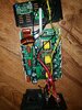
In any case, there seems to be 3 transformers with 2 mosfets per xformer. At least in quick testing, those mosfets seem to be OK. However, on the opposite site of the board there are 4 larger mosfets. 2 of those fets are hard shorted between all 3 terminals. There is also an odd bump on the side of one of the 2 main capacitors that looks suspect enough to pull it from circuit. I am also reading a short across those caps.

I realize in circuit testing will only go so far. I did notice there is a short between the input DC negative and one of the AC output legs and do not believe that was the case before the failure.

The 2 larger mosfets that seem shorted are 85GT33SW. When I look those up, all I can find are prices, no specs! Being a cheap China device, I have no doubt these fets are bargain barn and I would not mind throwing a little upgrade in to see if I can revive this thing. However, I have some concern if this will cause issues in functionality in the circuit. I planned to swap all 4 85GTs and the caps for low ESR SMPS rated pieces. I can try to get a pic uploaded here but I have poor service right now. Will try!

NOTE: I should mention I peeled the plastic wrap back on that one big cap, it didn't go bang! There is a slight bulge in the side that seems odd so I wanted a closer look.
 

Attachments

  • 20200515_001741.jpg
    20200515_001741.jpg
    2.8 MB · Views: 138
Last edited:
I am honestly pretty ignorant on how these work but I can only assume the DC comes in and an oscillator circuit kicks it to pure sine wave, then the little transformers boost the voltage up?
They are more complicated than that. In yours, the three transformers are in three parallel converters that boost the 12 V to around 170 V (for an output at 120 V ac). The current is shared between the three converters. The photo shows the three feed wires and the fuses near each transformer. The fuses look like they are red ATO automotive fuses, rated at 10 A, so that would only allow around 360 W

The transformers run at high frequency, probably around 50 - 100 kHz, and the three outputs are rectified and are in parallel after the rectifiers, giving the 170 V dc.

The four larger mosfets form an H-bridge switch the 170 V dc to give the 120 V ac. I think that they would use variable PWM to give the sine output, with the inductor attenuating the PWM frequency, leaving a cleaner 60 Hz output.

There should be isolation between the 12 V input and the ac output. Inverters are designed to have a floating output so that you can't get a shock from either output leg. You have to touch both, not just one and earth, to get a shock.

The transformers will isolate the power, and there seems to be an opto-isolator set at an angle above the transformers. That would be to give some sort of feedback from the output to regulate the input to the transformers. The fact that they have used and opto-isolator shows that isolation was intended.

If there is now a connection from the negative to the ac output, that would imply that an isolation component has shorted internally and isn't isolating. It could be that one of the transformers has shorted internally. I doubt that the opto-isolator would short, even if the LED or the photo transistor in it have failed. There could also be a capacitor or two between input and output to reduce noise, and they could have shorted. Or it could be that some wire has come away when you opened it up.

You should find out why there is a short from negative input to output, as it isn't safe to run it like that. The short from input to output can't be caused by failed semiconductors.
 
Thanks a ton! One thing worth mentioning and asking about is when the unit is switched off, there is no current, and when switched on, the inverter will 'try' to power up, pull high DC amperage, then fault and go back to zero.

I mention that because it does seem as though something still has some control over the circuit. The switch is a small rocker switch on the end plate with the AC output.

The fuses were pulled and verified to be 40A. Still have continuity of an AC leg to to DC-. I cannot imagine too many devices in the circuit that can handle 150A without complete failure.
 
A 1 kW inverter has to take around 80+ Amps at full power. By having 3 transformers, each bit only has to take around 30 A max, so the 40 A fuses will be fine. The outputs from the transformers are at 170 V so less than 10 A combined.

Continuity between an AC wire and and DC-ve might not stop the inverter working. However, it would not be safe without a proper ground connection, which isn't possible in a vehicle.
 
So if I understand this right, the control circuit will ramp up the boost section of mosfets, which generates PWM AC from 12V. that goes through the 3 isolation transformers, which boosts the voltage. It is then rectified and the H bridge creates the 4 quadrants of the AC waveform? I am still trying to determine how the DC- is getting coupled to the AC side right now if the transformers are in isolation. I hear what you are saying that it would seem a transformer may be bad, but so far I cannot find a leak in them.

As well, I am not detecting a full short between AC and DC-. There is about 1.5-2.0 ohms.

I did note that when I tore it down and switched the power switch on, there was residual power in the circuit that it attempted to power up for a second.

No, I do not believe AC was ever coupled to DC in any way when it was working. I recall meter testing that.
 
It's not quite right to say that the H bridge creates the 4 quadrants. It just creates ac.

A 4 quadrant converter is one that can create positive and negative outputs, and that can transfer power in both directions. Typically that applies to a DC motor drive that can control the motor forward and backwards, and can providing controlled braking in both directions.
 
I have removed the two suspect output mosfet and confirmed they are all shorted out. With them out of circuit, there is no communication of DC- and ac. However, it appears one pin on one bad one and one good one do connect to the dc-. ?? Obviously when 2 failed shorted, this caused the short between ac and dc.

In any case, I will probably have to try replacing the 4 output mosfet and just try it. I cannot find specs for the fets I listed in the first post. Can anyone advise? I dont want to use the same ones as they obviously failed and not sure if they are not quality parts or what. Rather use good components.
 
Last edited:
To be honest, I would scrap that inverter, no way it seems to be properly rated for 1000W. For example, I took apart an APC 2200W UPS, and the inverter section have 24 (count them - 24) 40A, 100V MOSFETs in 4 banks to create the 2200W of AC. Even at 1000W, you should have a lot more than 4 MOSFET drivers, just from the resistive losses alone on the circuit board. Just an opinion...
 
I have ordered a new inverter but I would like to gamble on this other one to see if I can revive it to keep as a backup. I cannot find the specs for the fets anywhere. No one has offered any help on the fets. I have two good ones still in circuit and curious if I can utilize them to determine suitable replacements? I realize the voltage and amperage will not be obtainable but I will never try to push this inverter in any way and the fets are bonded to the entire Aluminum enclosure so a light load should survive.

Any thoughts or recommendations?
 
Status
Not open for further replies.

Latest threads

New Articles From Microcontroller Tips

Back
Top