Continue to Site

Welcome to our site!

Electro Tech is an online community (with over 170,000 members) who enjoy talking about and building electronic circuits, projects and gadgets. To participate you need to register. Registration is free. Click here to register now.

  • Welcome to our site! Electro Tech is an online community (with over 170,000 members) who enjoy talking about and building electronic circuits, projects and gadgets. To participate you need to register. Registration is free. Click here to register now.

Light Modulator

Status
Not open for further replies.

COJohnson

New Member
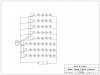
I have a simple circiut, which I can get to work with a single LED. The circuit uses a TIP31 to "switch" the light on and off when an audio input is used. With a single LED I can get this to work, but when I step it up to using either 4 or 7 LEDs, depending on the draw, it will onlt stay solid in color unless music is all the way up. I don't want to blow anything on the circuit or on the stereo so I am looking for any help as to why it wont work. The materials used are orange LEDs (1.8-2v), green LEDs (2.5-3.5v), TIP31s, and an audio connector both from radioshack. As it is set up the series of 7 LEDs are the orange and the series of seven are the green. Sorry for the crude schematic, kinda new at the whole thing. Any help would be appreciated. On the schematic the "L" "R" and "G" are in reference to left, right and ground on the input.
 

Attachments

  • Table+Schematic.jpg
    Table+Schematic.jpg
    281.7 KB · Views: 207
Last edited:
You are treating LEDs as if they were incandescent light bulbs.

Light bulbs are resistive in nature. They only draw as much current as thy need.

LEDs are semiconductors. They are not resistive in nature. If you were to hook a 2V LED to a 2V voltage supply it would draw as much current as the source was able to supply. If the current is too much the LED burns out. Or you might harm the supply.

To overcome this we use a supply with a voltage that is greater then LED or LED string and use a resistor to limit the current.

Lets say you have a 11 volt supply. You could use 5 LEDs in series with a Vforward (drop) of 2 volts. The LEDs require 10V of our 11V. We will drop the last 1V using a resistor. The resistor also limits the current for the entire string of LEDs. Current limiting is very important.

To calculate the needed resistance we need to know both the voltage drop, in this case 1V, and the current we want to supply the LEDs with. The current is specified in the datasheet. In many common LEDs 20mA.

Use ohms law

Resistance= Volts/Current = 1V/.020A = 50Ohms

So you would use a 56Ohm resistor which is the nearest available value.

This site has a calculator to make you life easier.

LED Resistor Calculator

EDIT: I did not look at the transistors to see if you are using them properly.
 
Last edited:
The transistors are also connected wrongly without a series base resistor.
The base-emitter of a transistor is a diode. Current flows in one direction and since there is no current-limiting resistor then the diode is shorting the output of your stereo and will probably blow it up.

The base-emitter diode of a transistor has a max allowed reverse voltage that is only 5V to 6V and the output voltage of almost any stereo will exceed this and blow up the stereo and the transistor.
 
Status
Not open for further replies.

Latest threads

New Articles From Microcontroller Tips

Back
Top