Continue to Site

Welcome to our site!

Electro Tech is an online community (with over 170,000 members) who enjoy talking about and building electronic circuits, projects and gadgets. To participate you need to register. Registration is free. Click here to register now.

  • Welcome to our site! Electro Tech is an online community (with over 170,000 members) who enjoy talking about and building electronic circuits, projects and gadgets. To participate you need to register. Registration is free. Click here to register now.

light dimmer

Status
Not open for further replies.

bogdanfirst

New Member
i need some special type of light dimmer.
i want to control some 12V lights, max. 4A(all lights). the dimmer will be controlled by 2 buttons. one will increase the light intensity, and one will descrease. also, it must have the ability to be controlled by some digital signal, 2 bits. one for increasing and one for discreasing the light intensity.
i thought of a 4029 counted and a PWM with a 555. but i don't quite know how to connect them together....
anybody can help me?
 
Bogdan - someone mentioned "digital pot" here a month or so ago and I found a design guide by Maxim (Dallas Semiconductor) on the web. I am left with the impression that a digital pot behaves as if it were the traditional pot except that the adjustment is done electronically and the resistance changes in discrete steps (though the increment is very small). The inputs on one type appear to be such that your up/down can be accomplished as you describe - in fact I think these were developed with that in mind for consumer electronics.

The power handling and range might be such that you could adjust a PWM circuit built from a 555 or similar common IC. Send me a message if you can't find the site and I'll send it to you.

An alternative - on the current version of the LM317 applications datasheet is a circuit that describes a "programmable" voltage regulator where multiple transistors are used to select a resistor that when selected or turned on, gives the desired voltage output. The more steps the finer the control of the light. You'd have to come up with the circuitry to select the right level. This is a bit more crude but if you've got the parts laying around it can be cheap. You'd have to wrap a power transistor around the LM317 in order to handle the power.

There is probably a slick way to do this with a PIC since some have PWM outputs but I haven't enough experience with them yet to offer much help.
 
i thought of using the pot.......but i loose a lot of power on it....low efficency. same on the LM317.
i want to use a PWM to control the light because it is more efficient. i can find a MOSFET wich can handle 4 amps as i need with no problem. using the LM317 with another transistor would mean quite a power loss.
the thing is that i need a 555 to be controlled by a voltage level.
sort of get a specific output from the timer, and the duty cicle modifies acording to that from something like 0-90% or something like that.
 
Good point on the power loss. I don't think the digital pot consumes much power - it appears they don't handle much power either but enough to control things in many applications.

I ran across the datasheet for a MIC502 which was designed for thermal management. Someone mentioned it here a while ago. The output is a PWM signal - from zero to 100% duty cycle. Input 1 is a thermistor but Input 2 can be a voltage input (therefore the digital pot, I think). Either input can be used to control the PWM output. The output is taken directly to the base of an appropriate power transistor. This might work for your lighting situation however the frequency that I noted is 30 Hz that might be noticed as a flicker. The digital pot might be expensive - or it might not.

I think your approach of putting a 555 to work in a simple configuration makes good sense - I just don't know how to offer you specific help. I've seen hundreds of 555 schematics - many that will do just what you describe. I just don't have one handy.
 
ok
so i will stick to the idea with the 555
the circuit is powered from 12V
so i need to create a 555 cirrcuit as a PWM and control the duty cicle with a voltage. vary it from 0% to more than 90%(i know i can't get 100% from 555)
if you can find one of those schematics that you say you have...
 
The 555 isn't the best IC to use if you want that range of duty cycles. There are many circuits that use op-amps. The typical method is to create a triangle wave and then use a comparator to determine where on the slope of the triangle the cut-off voltage is. Check this article out:

**broken link removed**

I can think of two ways to automatically control the voltage into the comparator: using a digital pot or using an ADC. If you go with a digital pot, check out the DS1804 from Maxim (formerly Dallas Semi). It's an incrementing/decrementing digital pot. If you go with an ADC, use the counter you talked about and go with an ADC that has a parallel interface (i.e. 8-bit). You can get either of these components fairly cheaply.
 
bogdanfirst said:
i need some special type of light dimmer.
i want to control some 12V lights, max. 4A(all lights). the dimmer will be controlled by 2 buttons. one will increase the light intensity, and one will descrease. also, it must have the ability to be controlled by some digital signal, 2 bits. one for increasing and one for discreasing the light intensity.
i thought of a 4029 counted and a PWM with a 555. but i don't quite know how to connect them together....
anybody can help me?
try this https://www.kitsrus.com/kits.html#k67 just change the motor with a bulb or light.try add some mosfet if you are using high load.
 
thanks dtb!!!!
it is just what i need. i have all the parts for it exept the MOSFET. just one thing.....
do i need a regulated 12V suply? just don;t want to use a 78l12. because i don't have it and it is preety hard to find it.
maybe a non stabilized power suply is good for what i need.
 
You don't need a regulated 12V supply. The 78L12 regulator is used if you have a 24V supply. In your case, you can omit it from the circuit. Incidentally, a 78L12 is a very common part so I'm surprised that it's not as easily accessible, even in Romania. Have you ever tried going through Digikey for parts (www.digikey.com)? I'm not sure how they handle international orders, but it may be worth some investigation. Also, most power switching MOSFETs will work in this application, as long as it can handle at least 4A (or 6A to be safe).

And I may be wrong, as Rookie pointed out, about a 555 not being able get the 0-90% duty cycle range you wanted. One thing I'm not sure about is whether you can get 0% out of the circuit shown. The lowest the CV pin will get is 1.56V (based on 12V supply) when the pot is turned all the way down. I'm not sure, just asking.
 
thanks!
this is why i thought the 12V reg is there for. the idea is that i want to use the outputs from a 4029 and with some voltage dividers to get the duty cicle i want.
about the 78L12.....well it is not the problem that it is not avgailable. the idea is that i am living in a quite small town, so the shops for electronic components are not so rich here. so i have to order the components over the internet. they usually arive in 3-5 days. it is a common component as you say. but i can't order just it as a single, though i could oreder a few more to have spare. but still...shipping will cost more than the component itself. anyway, i have a lot of 7812 so i will use one of these till i need to order more components and order the reg too.
now, the 555....yep, you are right. it cant get 0-90%
actually i needed 0-100%, but i know you cant get that. the widest range of pmw i have seen was from 20 to 90%. i need from 0.
now all i have to do is make a voltage divider and get some resistors from the 4029 to get the appropriate modulation.
 
more on light dimmers

Here's another dimmer circuit to look over:

**broken link removed**

replacing the pot with an inexpensive Epot would allow digital control. Any schmitt-trigger gate will work in this circuit (The TC7WH14FKCT from Toshiba has three ST inverters in a tiny 8-pin package). I tend to like the schmitt-trigger based designs for their simplicity.

- CAL
 
Another Option would be to use a DC/DC converter circuit with a variable inductor or potentiometer, depending on the type of DC/DC converter you're using. it is only 90% efficient, but if the PWM is not producing nice effects, then it's a possibility.

Otherwise just use a PWM system and put a 2nd order Butterworth filter on the end of it. You can do this with 2 caps, 2 resistors, and one dual comparator, if memory serves.
 
a thought

Spline, your comments seem to be directed at the "noisy" performance of PWM controllers in general. As far as lamps or DC motors go, the load essentially incorporates the low-pass filtering for free. For LEDs and such, choosing a PWM frequency above what the human eye detects as "flicker" is necessary. I used to think 30Hz was adequate, but recently ran across a medical article that suggested 5 - 100Hz is a dangerous zone for photosensitive epilepsy (~ 10% of epileptics, according to the study), with around 50Hz being the worst trigger point. It may not be a bad idea to keep those multiplex rates above 100Hz.

Another means of lowering filter constraints at the extremes of modulation (near 0 or 100%) is to use a numerically controlled oscillator instead of pulse-width modulation. Basically, you replace the counters in the classical digital PWM with modulo (wrap-around) adders. Also called "distributed" PWM, this technique has been described several times in the 90's design literature (EDN), both for use with micros and with discrete logic.

OK, here's the thought:

It's amazing to me how simple tasks like a light dimmer, driving a 7-segment display or a hay-baler (another recent thread) can generate such interest and different ways of solving a given problem.

I found myself getting a little annoyed at the lamp-dimmer thread, since it seemed to be a purely digital problem to me (I have a large digital hammer and everything looks like a nail). Two pushbuttons in (digital) and PWM out (also digital). From a design standpoint, it seemed asthetically wrong to convert to the analog domain and then back to digital in order to solve the problem.

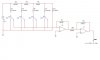
In fact, I came up with a simple, purely digital solution using a couple of inexpensive HC logic IC's. Rather clever too, I thought.

Then, I ran across the links I posted recently. EPOTs are ubiquitous and cheap these days, unlike the situation several years ago. Coupled with a simple schmitt-triggered astable multivibrator, it was a nail in the coffin.
I guess my point is to follow the Occam's razor principle, and try to go with the simplest solution that will do the job reliably. Not exactly what Sir William said, but close enough.

Try not to get married to your ideas, just because they're yours. I think there's a tie-in with the not-invented-here (NIH) syndrome.

- CAL
 
thank you for your replies. i appoogise for not answering for some time, but i was gone for a couple of weeks in a camp.
ok, now i see more circuits. the one with the inverter, 74C14 seems a lot simpler. the one with the led dimmer seems ok, but i think i will have some problems with getting the parts. so i think that i will stick to the one from tdb. i got all the parts for it and it seems to do just what i want.
so now i am stuck to another problem. i require to control it from a digital circuit. as i see from the schematic i need to apply a voltage from 2.6 to 9.4 to the inverting input of U1b. i will have to generate this voltage from 4 digital outputs, wich will have 12V for H and 0V for L.
any1 knows how to do this.
 
I would recommend a 4-bit D/A converter with a parallel interface for the input switches. But I know you said your parts availability is limited, so you can actually build your own using a circuit called an R-2R ladder. Check out the circuit below. It's best to use 1% tolerance resistors if you have access to them. This circuit will give you an output of 0-11.25VDC, in increments of 0.75VDC for each binary number from 0-15. The switch on the far left (D) is the MSB, and the switch on the far right (A) is the LSB. Connect the output directly to the inverting input of U1B.
 

Attachments

  • R-2R_LADDER.jpg
    R-2R_LADDER.jpg
    31.6 KB · Views: 2,456
that's what i want. just that i want to take the output from a 4029 counter. it would be easy if i had a counter like 4017 but wich can count both up and down. know any IC wich can do this?
 
up/down decoded counters

The only standard up/down counters I'm aware of are binary or decade. The Johnson-type counters like the 4017 and 4022 only count up. It's not easy to turn them into down-counters because the outputs have already been decoded internally.

Try combining a 4-bit binary U/D counter (CD4029, HC191/193) with two 3:8 line decoders (HC138), or a single 4:16 decoder (HC154).
 
The DAC is a good idea, but I think an R-2R ladder is overkill for a low speed, low resolution (4 bit) application. Here's a simple DAC you can connect directly between your counter and your comparator in the PWM circuit. Make the resistor values large so that the output resistance of the counter is insignificant. I would make R at least 50k and pick the nearest 1% values. For example:

R=100k
2R=200k
4R=402K
8R=806k

Many other combinations will work.

Both of these DACs are designed to work with binary counters, so a counter like a 4017 wouldn't work, even if it did have up/down capability.
 

Attachments

  • 4bit_dac.gif
    4bit_dac.gif
    3.2 KB · Views: 2,439
nice idea

Simple idea, Ron. I like it. Looking at the end goal instead of just answering posted questions with 1-for-1 answers makes everyone happy sooner. It's hard if the posting doesn't provide a good description of the problem. Then it's more like playing "twenty questions". I'm not picking on Bogdan, his posts have been clear and to the point.

I still like the schmitt-trigger solution... :wink:

- CAL
 
Status
Not open for further replies.

Latest threads

New Articles From Microcontroller Tips

Back
Top