Continue to Site

Welcome to our site!

Electro Tech is an online community (with over 170,000 members) who enjoy talking about and building electronic circuits, projects and gadgets. To participate you need to register. Registration is free. Click here to register now.

  • Welcome to our site! Electro Tech is an online community (with over 170,000 members) who enjoy talking about and building electronic circuits, projects and gadgets. To participate you need to register. Registration is free. Click here to register now.

Lifepo4 battery charger MCP73X23 Evaluation Board went up in smoke

Status
Not open for further replies.

Electrocub82

New Member
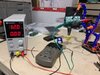
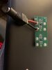
I purchased a Microchip MCP73X23-LCP evaluation board. This board charges LIFEPO4 (Life) batteries.. There are two parts to the board, the MCP73123 IC circuit which charges a single battery and a MCP73223 IC circuit which charges 2 batteries in series. I connected a barrel connector to the MCP73223 board, positive to the vdd connector and negative to the vss connector. The transformer (wallwart) was 16 volts/1 amp. I didn't have a battery connected when I tested the board to make sure I wasn't going to damage the battery after I plugged it in. When I plugged it in, the MCP73223 ic smoked (I released the magic smoke). I checked my connections and they appear to be correct. The wallwart is a center tap positve, the center of the barrel connector is positive and was connected to vdd. The barrel is negative and was connected correctly to vss. Even though the data sheet says that it can be powered up to 18 volts, I thought maybe 16 volts might be too much. Then I used my bench power supply. I set the voltage to 12 volts and connected the red to vdd and black to vss on the MCP73123 side of the board. Again, the IC smoked and stopped working. I have included 2 pictures to look at, the first picture is the barrel connector to the MCP73223 side to show the way that I connected the power supply to the board. The second picture is a picture of my power supply and the voltage that I had applied to the MCP73123 side of the board. I attched a link to the datasheet since I cannot copy the schematic in a legible manner. Any thoughts why I had problems today? Did i use too much power? Is VSS positive and VDD negative? According to the internet, VSS should be negative and VDD should be positive. Thanks
 

Attachments

  • MCP73123 Connection with bench power supply.jpg
    MCP73123 Connection with bench power supply.jpg
    37.2 KB · Views: 186
  • MCP73223 connection.jpg
    MCP73223 connection.jpg
    10 KB · Views: 192
I agree that the photos are too small.

The 16 V wall wart could have been putting out more than 18 V, which could have blown the device.

I've found the evaluation board (https://www.microchip.com/DevelopmentTools/ProductDetails/PartNO/MCP73X23EV-LFP) and it's wired to the power supply the wrong way round, which will kill the device.

Vss is negative, and Vdd is +ve.

If you are wiring up a battery charger to a power supply you can start with the current limiter being really low, like 10 mA. Then the power supply probably won't kill the load if you connect the wrong way round.
 
Diver300, thank you! You are right. I did have the power wired backwards. I also will use a variable power supply and cut the voltage down to 12 volts for the MCP73223 side of the charger.
I got a new board a day ago. I also got new MCP73223 IC's. I am going to try my hand at soldering DFN chips and replace the blown chips with the new chips. I've had a hot air soldering station for over a year and haven't tried it yet. This will be a good experience.
Thanks again
 
I got the new board, and after running the power the correct way it worked. Then I got new MCP73223 chips (the two cell chargers) and soldered them to the boards after I removed the bad IC's and they work. I learned some new lessons from this project. Thanks to all!!!
 
Status
Not open for further replies.

Latest threads

New Articles From Microcontroller Tips

Back
Top