Hi,
I have a circuit that turns a lamp on and off dependent of fuel level.

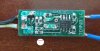
I removed the caps for better viewing:

Superimposed the back of the board in RED:

My attempt at a layout and details of components:

The switch is a reed switch with a float and magnet acting on it, when the switch closes the low fuel lamp on the dash should light up.
The fault is the fuel level low light didn't work, I disassembled the sensor, dug out the board that had been fully potted.
Action taken:
Replaced the 2B transistor with a 2FZ because I pulled the 2B off when cleaning the board. I was assured the 2FZ would be comparable.
Replaced the two electrolytic capacitors which smelled of gasoline.
Replaced the LM393 comparator chip.
Now the low fuel light is always on and will not go off regardless of the fuel level switch state.
The markings came off a couple of the components, hence the ?'s
On another forum a member made a circuit diagram (below) and suggested the following before the thread was closed due to AAC forum rules:
I believe one or both of your capacitors' polarities are reversed. If you measure the trace where you connected to the negative side of your caps with the +12 using an ohm meter, what is the resistance you get?
The 2B transistor is an PNP equivalent to 2n2907 so is 2F(z). But the Base of the transistor should not be connected to the input of the comparator (P3). I redraw your circuit with proteus and I guess it is much easier to understand.

Here is a photograph of the board after I dug it out from the potting and it looks like the electrolytic caps are the same polarity as i connected the replacements and put on my diagram:

I didn't fully understand the statement "If you measure the trace where you connected to the negative side of your caps with the +12 using an ohm meter, what is the resistance you get?" Can anyone tell me where to measure the resistance physically ie one probe on the -ve of the caps, where for the other probe ?
Thanks
I have a circuit that turns a lamp on and off dependent of fuel level.
I removed the caps for better viewing:
Superimposed the back of the board in RED:
My attempt at a layout and details of components:
The switch is a reed switch with a float and magnet acting on it, when the switch closes the low fuel lamp on the dash should light up.
The fault is the fuel level low light didn't work, I disassembled the sensor, dug out the board that had been fully potted.
Action taken:
Replaced the 2B transistor with a 2FZ because I pulled the 2B off when cleaning the board. I was assured the 2FZ would be comparable.
Replaced the two electrolytic capacitors which smelled of gasoline.
Replaced the LM393 comparator chip.
Now the low fuel light is always on and will not go off regardless of the fuel level switch state.
The markings came off a couple of the components, hence the ?'s
On another forum a member made a circuit diagram (below) and suggested the following before the thread was closed due to AAC forum rules:
I believe one or both of your capacitors' polarities are reversed. If you measure the trace where you connected to the negative side of your caps with the +12 using an ohm meter, what is the resistance you get?
The 2B transistor is an PNP equivalent to 2n2907 so is 2F(z). But the Base of the transistor should not be connected to the input of the comparator (P3). I redraw your circuit with proteus and I guess it is much easier to understand.
Here is a photograph of the board after I dug it out from the potting and it looks like the electrolytic caps are the same polarity as i connected the replacements and put on my diagram:
I didn't fully understand the statement "If you measure the trace where you connected to the negative side of your caps with the +12 using an ohm meter, what is the resistance you get?" Can anyone tell me where to measure the resistance physically ie one probe on the -ve of the caps, where for the other probe ?
Thanks
Last edited:


")


