Continue to Site

Welcome to our site!

Electro Tech is an online community (with over 170,000 members) who enjoy talking about and building electronic circuits, projects and gadgets. To participate you need to register. Registration is free. Click here to register now.

  • Welcome to our site! Electro Tech is an online community (with over 170,000 members) who enjoy talking about and building electronic circuits, projects and gadgets. To participate you need to register. Registration is free. Click here to register now.

LED voltage meter LM339 design question

Status
Not open for further replies.

namezero111111

New Member
Hello folks,

I just registered for this forum.

I am trying to design a circuit to determine lead-acid battery charge level.
I determined that at 77*F, a 100% charge would be 12.63V, and a 50% charge would be 12.00v.
I also have data for every 10%.
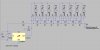
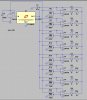
I designed the circuit as indicated in the attached file, and have tested it in LTspice, which indicates that the circuit would work (see the second picture).

However, I believe that this circuit is very difficult to built (it seems cumbersome). I have read about the LM3914 (?) that can be used to drive a bar display, but I don't think it could measure such small voltage changes that are also non-linear.
So I was wondering, if I were to build this, is there any better way than using odd resistors like 6579 or 7353 ohms? I'd have to be very close to those values so that the bar display is reasonably accurate.

I've also seen designs where the voltage divider on the measured side is "cascaded" instead of every comparator having its own little voltage divider. If I were to make such a design, how would I calculate the values of the resistors required?

Do you see any problem with the design as is? I might be worried about the low current in the diodes as indicated on the diagram, would that be a problem?

Thank you all for your help in advance!

-namezero
 

Attachments

  • Circuit2.jpg
    Circuit2.jpg
    180.4 KB · Views: 524
  • Circuit.jpg
    Circuit.jpg
    186.8 KB · Views: 939
  • Draft2.asc
    9.1 KB · Views: 311
Last edited:
hi,
The LM3914 can be 'offset' such that it works over a limited range of input voltage.
eg: can be set for 11V thru 13V, so that the 10 LED's represent a 2Volt input span.

Is this what you have in mind.?:)

EDIT:

Check the polarity of the LED's in your schematic, they are the wrong way around.

AAesp01.gif
 
Last edited:
Indeed they were. I didn't know the LM339 couldn't source current. I found that in another thread. That way around it seems to work. But now the the lights come on when the voltage is BELOW the threshold, not above it.

When I swap the +/- inputs on the 339, LTspice shows some dramatic noise where is oscillates back and forth on the transition, even if I put a resistor for hysteris in there.

The reason I was using the 339 and not the 3914 is that this way I can learn a lot more about what is going on instead of using a microcontroller and having no idea. I'm also trying to advance myself a little in the field of simple electronics : )

And by the way, the way you drew the circuit looks so much cleaner!!

So I guess my only question remains, how would one better approximate the values of the resistors?
My idea was to use a math program called Derive6 and ruthe voltage divider formula through it.
(i.e. 5.0 = 12.36 * R1/(R1+R2) and then create a table with R1 in 100 ohm steps or so and looks for a value where I can match R2.
But I am sure there is a better solution out there.

Thank you again!

-namezero

hi,
The actual LM3914 uses a resistive chain to create the individual comparator reference voltages.

By driving the chain with different voltages it effects the individual switching points.

Why dont you explore that method.?:)
 
I want to. I am still a little confused about the resistor chain, but am looking into it right now actually.
My confusion arises from the fact that R1 for each successive 339 increases, so R2 must increase, too.

I found a document that says that V_i=i/N * V_ref for equal resistors.
I am currently looking into that, and the diagram here: here.

I need the voltages to be 12.6 12.5 12.4 12.24 12.12 12.00 11.9 11.8 volts, so there is a slight divergence from a linear relationship in the middle, and I am trying to figure out the math for the resistors in such a chain.

Thank you!

-namezero

hi,
Looking at your voltage list it appears to have three groupings of steps.
Why not use three Vrefs to drive three separate resistor chains, one for each group.?

Code:
[B]12.6 12.5 12.4  0.1v    12.24 12.12 12.00 [/B] .12v  11.9 11.8 0.1v [/B]
 
Last edited:
Attached is a similar circuit which required non-equally spaced trip points. However, look at the schematic. You might pick up a couple of pointers about how to add a little hysteresis at each trip point. Note how I used a behavioral voltage source to create a non-linear function.
 

Attachments

  • FlapIndicator.gif
    FlapIndicator.gif
    86.1 KB · Views: 613
Thank you so much!

I solved the problem by placing one 100 ohm resistor in the chain and 62 ohms otherwise.
The plot for all voltages is almost identical to the one I had before with separate dividers.

I only have one problem now, that is when the diodes switch on and off I get hysteris problems over a few milliseconds. I tried adding a 220k resistor from the output to the + terminal of the comparator, but that had no effect.
Is that something that only occurs in simulation but would make no difference in real life?
It just bothers me because it causes the simulation to run very slowly.

What do you think of this circuit now?


-namezero
 

Attachments

  • Circuit2.jpg
    Circuit2.jpg
    223.5 KB · Views: 252
  • Circuit1.jpg
    Circuit1.jpg
    428.7 KB · Views: 332
  • Voltmeter_Test.asc
    6.5 KB · Views: 213
Thank you so much!

I solved the problem by placing one 100 ohm resistor in the chain and 62 ohms otherwise.
The plot for all voltages is almost identical to the one I had before with separate dividers.

I only have one problem now, that is when the diodes switch on and off I get hysteris problems over a few milliseconds. I tried adding a 220k resistor from the output to the + terminal of the comparator, but that had no effect.
Is that something that only occurs in simulation but would make no difference in real life?
It just bothers me because it causes the simulation to run very slowly.

What do you think of this circuit now?


-namezero

hi,
You have the INV and NI inputs crossed over, you cannot apply hysteresis from the outputs to the NI inputs because you have them decoupled to 0V via that power rail.

EDIT:
This is a simple example of an equally spaced Vgap, note the comp input sense

Use the method as shown by MikeL
AAesp04.gif
 
Last edited:
I see. So where I have it connected to + I should have connected it to - and vice versa, right?

The reason I did it this way is because otherwise the diodes light up when they shouldn't and vice versa.
I had it the other way around before.

Hm maybe I am still confused as to the operation of comparators. Non-inverting is the + input right?
I am a little new to this : ) Sorry if I ask irrelevant questions.
 
Thank you! Everything works, I just built the circuit.
I had never used a computer program before, to check circuits, I didn't know they existed for free.
First time I built a circuit and it worked right away!! This is much more fun!

Thank you!

Now I will add a timer so you can push a button and the voltmeter stays on for let's say 20 seconds!
 
Last edited:
Status
Not open for further replies.

Latest threads

New Articles From Microcontroller Tips

Back
Top