Continue to Site

Welcome to our site!

Electro Tech is an online community (with over 170,000 members) who enjoy talking about and building electronic circuits, projects and gadgets. To participate you need to register. Registration is free. Click here to register now.

  • Welcome to our site! Electro Tech is an online community (with over 170,000 members) who enjoy talking about and building electronic circuits, projects and gadgets. To participate you need to register. Registration is free. Click here to register now.

LED voltage measurement question

Status
Not open for further replies.

Lucky-Luka

Member
Hi all
I'm starting building simple circuits to better understand the theory related to them.
As soon as i've finished my first ever super simple circuit something isn't clear at all...
I'm talking about my LED voltage measurement.
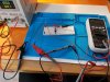
I have a breadboard with a 5V power supply attached.
When the power supply is disconnected from the board and when the button on the breadboard is pressed and the power supply is attached to the breadboard I can assume that what I read in the voltmeter is right but I cannot understand what's going on when the power supply is attached to the breadboard and the button on the breadboard is not pushed. Why do I read -1.308V (power on) and -1.496V (power off)?
Thanks for your help.

Luca

1_89V.jpg-1_308V.jpg-1_496V.jpg29_8mV.jpg
 
There are several effects happening here.

1 Your voltmeter has a high impedance input.
This is normally a very good thing, but under some conditions, very small stray currents can make the high impedance voltmeter display some odd voltages.

2 Your "power supply" I guess is powered from a cheap "Wall Wart".
These things can be a problem in that they are not earthed and there can be stray voltages on the output.
The output may be a good solid 5v or whatever the PSU is designed for, BUT, the whole output can be many volts above earth potential.

I suggest that you try to power your circuit using batteries.
I think that you will not have this problem.

JimB
 
Maybe the breadboard has intermittent connectors.
I agree with using a battery like I always do to measure the forward voltage of an LED.
 
I think you are right... my 9V 1A power supply connected to the breadboard power supply module is cheap.
When I touch the power supply module I obtain the desired result so... it's not earthed!
I've learned something!
Is there a way I can earth the system so that I can use this PSU or do I have to upgrade it with something better?
Thanks

Luca
 
The power supply has some capacitance which means it will retain a voltage, possibly for some time without a load.

You need to put your voltmeter across the power supply and watch it's decay when powered off. If you want it to decay quicker, you have to remove the secondary power or add a load resistor.

A linear supply would have a time constant of R*C. The capacitance and the equivalent R. At 5*R*C about 99% of the voltage would be gone accross the capacitor.

I hope I've understood what you mean. There is no relavant voltage measurable from the pins of the power supply module when it's OFF however there is more than 1V drop across the LED.
I think it's related to stray voltages as JimB said.
Btw is there a way to get rid of stray voltages in my tiny project?

Luca
 
Any voltages you read with the supply off are just noise and not important.

Mike.
 
I think it's related to stray voltages as JimB said.
Yes, the problem is not due to supply hold up because of the reservoir capacitor, it is a stray voltage due to the interwinding capacitance of the transformer in the PSU.

I just did a quick test on a couple of wall wart type power supplies which I have here.

PSU #1
Output = 14V DC
Voltage between negative side of the output connector to mains earth 9V AC

PSU #2
Output = 9V DC
Voltage between negative side of the output connector to mains earth 7V AC

The voltage between the negative side of the output and earth has a high impedance source and will not cause any problems in the normal intended operation of the PSU.
However, when using a high impedance voltmeter, this stray voltage can cause some strange readings.

Btw is there a way to get rid of stray voltages in my tiny project?
Yes.
You could connect a wire from the negative side of the supply on the breadboard to something which is connected to earth.

JimB
 
I have upgraded a little bit my system.
The problem is gone: 59mV voltage read, which is ok.
Thanks everybody.

Luca
 

Attachments

  • 59mV.jpg
    59mV.jpg
    606.5 KB · Views: 93
Status
Not open for further replies.

Latest threads

New Articles From Microcontroller Tips

Back
Top