Continue to Site

Welcome to our site!

Electro Tech is an online community (with over 170,000 members) who enjoy talking about and building electronic circuits, projects and gadgets. To participate you need to register. Registration is free. Click here to register now.

  • Welcome to our site! Electro Tech is an online community (with over 170,000 members) who enjoy talking about and building electronic circuits, projects and gadgets. To participate you need to register. Registration is free. Click here to register now.

LED tail light conversion question

Status
Not open for further replies.

Isoproturon

New Member
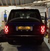
I am converting a 2008 Range Rover from filament rear lights to the later LED clusters. I have run into the following issue and would appreciate some help.

The original lights used a 5W supply to provide the tail lights, increasing to 21w when the fog light switch was pressed. It is a standard 12V system.

On the new lights the tail lights (outer rings) and fog lights (centre of the lower ring) are separate. There is a wire for fog lights and one for tail lights. When switching the tail lights on, they come on but the centre section which is only meant to illuminate as a fog light (when switch pressed) comes on in a low power mode. It gets brighter when the fog switch is on.

I would like to ensure this centre section only comes on when the fog light is switched on, as it is not needed due to the fact it has separate tail lights.

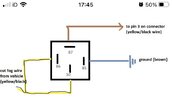
Reading up, it appears that a simple relay circuit could solve this but I am under the impression it needs a diode and resistor adding.

Not quite sure where to start, working out what specification and what components are also needed.

If anyone could help I would be very pleased!
 
The photo shows the tail lights (fog light wire disconnected, otherwise the centre of the lower ring comes on at low power at this stage).
 

Attachments

  • 771D68DC-8106-414F-BFA9-CF618D0FF0C9.jpeg
    771D68DC-8106-414F-BFA9-CF618D0FF0C9.jpeg
    915.6 KB · Views: 151
The other question, is what is the best way of stepping the 12V supply down to around 6V for the cluster overall, as I think the LEDs are meant to be used at the lower voltage?
 
I don't think that you need to reduce the voltage when the lights are turned on. The cluster has to be designed to work on a 12 V system.

It is likely that add a low power resistor from each light wire to ground will deal with the problems.

I suggest 68 Ohm 10 W resistors. They will run at 3 W, but they will still get hot.

Cars of that age often supply some current to lights that are turned off, in order to detect if the lamp is working. That current is too small to illuminate an incandescent bulb, but will make an LED light glow or illuminate. A resistor will take the current and keep the voltage low.

The fog light section of the LED lights may be taking power from the sidelight section when it sees some voltage on the fog light wires. A resistor should stop that.
 
If the side lights come on when needed, and the fog lights turn off when disconnected, a relay for the fog lights would be a simple solution. You don't need a relay for the side lights.

On the normal relay numbers, one way to connect it up is:-
85 - ground
86 - from existing feed
87 - from existing feed
30 - to fog light
 
The fogs come on at low power with the sidelights but if I disconnect the foglight wire they go out and the sidelights stay on. When they are connected, and the switch is pressed, the fogs get brighter.

To power the relay there is only really the foglight wire.
 
From what you've said, a relay connected as I've described should work.

When the fog lights are off, the relay contacts will be open, disconnecting the fog light wire to to the light cluster. When the fog lights are on, the relay contacts will close, powering the fog lights.
 
The sounds good, and what I’d hoped. I wasn’t sure if the current going through the foglight wire to drive what would’ve been the 5W filament bulb in the old clusters would trigger the relay.
 
If the side lights come on when needed, and the fog lights turn off when disconnected, a relay for the fog lights would be a simple solution. You don't need a relay for the side lights.

On the normal relay numbers, one way to connect it up is:-
85 - ground
86 - from existing feed
87 - from existing feed
30 - to fog light
I’ve attached a diagram that someone posted on one of the Range Rover forums years ago - would that work as well as the way you suggest, out of interest?
 

Attachments

  • 2EF01627-D4F3-492D-8DB1-D83C8A74BCF9.jpeg
    2EF01627-D4F3-492D-8DB1-D83C8A74BCF9.jpeg
    42.8 KB · Views: 149
I’ve attached a diagram that someone posted on one of the Range Rover forums years ago - would that work as well as the way you suggest, out of interest?
Yes it would.

If you are using a normal 4 pin relay, you can swap 85 with 86 and it makes no difference. You can also swap 30 with 87 and that makes no difference.

The diagram you posted would be the same as the way I had suggested if 30 and 87 were swapped, and as those two can be swapped, the two ways will work equally well.
 
The sounds good, and what I’d hoped. I wasn’t sure if the current going through the foglight wire to drive what would’ve been the 5W filament bulb in the old clusters would trigger the relay.
The current coming from the car on the fog light wire has to be too low to illuminate the fog lights at all, or they would glow all the time in a standard car.

The current will only be a few mA. That is enough to make the LED fog lights glow, but not enough to turn on the relay. With the relay off, the circuit to the fog light will be cut, as it was when you took the photo.
I’ve been thinking about this - on the old lamps the fog light wire provides enough to light a 5W filament in the 21w/5w bulb and the tail light wire lights a 5w single filament bulb, the two together making up two halves of a circular tail light. When the fog switch is pressed, the 21w filament lights up in addition, for the fog light.

Therefore it’ll be more than a few milliamperes.
I may not have made myself clear, as I meant that the fog light wire is supplying some current when the fog lights are off. It is when the fog lights are off that a few mA is provided by the wire, which is not enough to make the 21W bulbs glow, but is enough to make the LEDs light, at least partially.

It's clear that the wire will provide up to around 2 A per side when the fog lights are on, as that's what makes them light up. The problem you have is when the fog lights are off.
 
Well, this sort of worked.

With the relay, the centre of the lower light didn’t come on with the tail lights. So far, so good, except the relay was making a lot of noise.

When the fog light was pressed, the lower half of the light came on (at a low level) and the upper part didn’t illuminate. In other words, the fog light didn’t function correctly.

Not sure where to go from here.
Draw the circuit out three times. On one, show the voltages at each point with the ignition on and the lights off. On the second show the voltages with the ignition on and the side lights on. On the third, show the voltages with the ignition, side lights and fog lights on.

Post some photos of the connections, and the wires to the lights.

When you refer to upper and lower halves, are those fog and side or what?

Relays are generally silent unless actually in the process of switching on or off. Is the relay making a noise all the time that the sidelights are on?
 
I will try and get something sketched out as you suggest.

Old lights - tail light is a circle of two halves. Tail light wire lights a 5W bulb in one half when switched on. In addition, the foglight wire passes current to the 5W filament in a twin filament bulb in the second half. Both halves illuminate. Pressing fog light powers the 21w filament via the foglight wire.

New lights - tail light wire illuminated two hollow rings for the tail lights. If the fog light wire is connected, half the centre of the lower ring illuminates at the same time - in other words the fog light wire becomes live with the tail lights being switched on. If you press the fog light switch, the half that is lit glows brighter.
 
Status
Not open for further replies.

Latest threads

New Articles From Microcontroller Tips

Back
Top