Continue to Site

Welcome to our site!

Electro Tech is an online community (with over 170,000 members) who enjoy talking about and building electronic circuits, projects and gadgets. To participate you need to register. Registration is free. Click here to register now.

  • Welcome to our site! Electro Tech is an online community (with over 170,000 members) who enjoy talking about and building electronic circuits, projects and gadgets. To participate you need to register. Registration is free. Click here to register now.

LED Reverse Polarity detector with buzzer indicator

Status
Not open for further replies.

selva prabhu

New Member
Hi all,
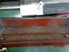
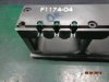
Required your help to do a simple project to detect a reverse polarity of thru hole LED for testing 12 individual LED in a fixture .
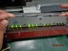
Currently we use manual kit with pogo pin give which is connected seriously with external DC power supply source,so when we insert fixture with LED to the kit ,it will contact to the pogo pin and light up.
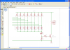
Required your assistance for building simple project to detect any reverse polarity or no light up with a buzzer sound .
 
12 individual LED in a fixture .
How are they wired within the fixture? What are the LED ratings? What is the power supply rating?
Show us the circuit.
 
Hi kindly refer the attachment ...the manual kit pogo pin in connected serial and connected to the power supply source (2v/120mA).
 

Attachments

  • Manual kit.JPG
    Manual kit.JPG
    160.5 KB · Views: 426
  • fixture.JPG
    fixture.JPG
    162.6 KB · Views: 433
  • light test.JPG
    light test.JPG
    161 KB · Views: 441
Get 12 LDR's and wire them seriously and connect them to a transistor amplifier and a piezo. It will scream when a LED does not illuminate.
 
Here is a circuit to test 8 LEDs at a time. (could be 12 or more)
I am using a 5 volt charger for power. (many LEDs can with stand no more than 5 volts reverse voltage)
I am using 220 ohms to light the LEDs at 10mA. (more or less)
The pictures show green LEDs so the forward voltage drop is in the 1.8 to 2.6 volts range.
I am using one LED of the same type as a Zener diode. (to drop the voltage going to the base of Q1)
If all the test points are connected to LEDs pointing the right direction LED1 and Q1 and Buzzer will all be off.
If one or more LEDs are backwards or not connected then the buzzer will sound.
upload_2016-4-5_22-43-35.png

Formula: (voltage drop of D1-8) + (voltage drop of B-E of Q1) + (LED on voltage of LED1) = buzzer on voltage.
So if one of the LEDs under test has a voltage drop of 1.3 volts too much the buzzer will sound.

Is this what you want?
 

Attachments

  • upload_2016-4-5_22-43-0.png
    upload_2016-4-5_22-43-0.png
    43.2 KB · Views: 446
Hi,
the above schematics can able to test only Green colour LED only or other colours also able to test.
The power source for tetsing LED we use the separate Agilent power supply .
These are the following voltage and current we set in Agilent power supply for testing LEDs
Red colour --2V/120 mA
Green ----2.1V/120 mA
Yellow----2.2V/120 mA
Blue----3.5V/120 mA

Form the above circuit any modification need to be done for detecting reverse polarity .
Or can be used for all other colours. kindly assist me.
 

Attachments

  • power supply ag.JPG
    power supply ag.JPG
    29.3 KB · Views: 405
I used a green LED in the tester because I needed a 2 volt Zener and they are hard to find. But a green LED is a 2 volt Zener.
The "turn on buzzer" voltage is two diodes drops above the reference green LED.
0.67V + 0.65V=1.3V
I think you could use a yellow LED for reference and test red, green and yellow LEDs just fine. But the Blue will fail.

New specifications so new circuit:
Using a voltage comparator.
With a 5V supply, set the pot so it outputs 3.3V. This will set the trip point at 3.3+0.7=4V. Now it is looking for any voltage larger than 4 volts. (the LM393 will not work if the pot is set to more than 3.5V "input common mode voltage limit")
So this circuit is looking for a voltage larger than 4V. A red LED will have 2.0V and will pass. I think this will work.
I don't know how much current and voltage the buzzer needs and if the LM393 will drive it.
If you need a trip voltage higher than 4.2V then I need to change something.

upload_2016-4-8_7-27-9.png
 
Isn't it a requirement that the automatic tester determines that each of the LEDs under test actually light up?
 
Isn't it a requirement that the automatic tester determines that each of the LEDs under test actually light up?
It is testing for voltage drop.
If the LED is missing (open) the buzzer will sound.
If the LED is backwards the buzzer will sound.

The only fault I see is if the LED is shorted. It will not test for that.

If you really want to test for light....more circuits.
simple project to detect a reverse polarity of thru hole LED for testing 12 individual LED in a fixture
 
Hi ,
ronsimpson
Kindly clear my doubts.
if we pass voltage and current in reverse polarity LED and with DC source (power supply) of 2v /10mA and test the LED lead with multimeter there will be flow of voltage still but no light up . But if we test the current it be zero , is that any circuit to detect current of the LED individually ,Or this above circuit will work .
Please advise
 
...Kindly clear my doubts.
if we pass voltage and current in reverse polarity LED and with DC source (power supply) of 2v /10mA and test the LED lead with multimeter there will be flow of voltage still but no light up . But if we test the current it be zero , is that any circuit to detect current of the LED individually ,Or this above circuit will work .
Please advise

Back to Basics:

If you apply 2.0Vdc (current-limited to 10mA) Cathode to Anode to a good LED, there will be almost zero current flow regardless of the Vf of that particular LED...

If you apply 2.0Vdc (current-limited to 10mA) Anode to Cathode to a good LED, there might be almost zero current flow if the Vf of that particular LED is 2V or greater. There might be significant current flow if the Vf of that particular LED is less than 2V.

This means that 2V is not a good test voltage for determining which way a LED is connected. current flow...

Here is a better method:

LEDt.gif


There are four possibilities as shown above.

Note that the 4.5V was carefully chosen to be greater than the Vf of any LED I have seen, but less than 5V, which is the "never-exceed" allowed reverse voltage that can be applied to most LEDs without damaging them (at least, not without limiting the current to a few tens of uA).

Unfortunately, by looking at the voltage at B or C, you cannot tell if the LED is installed reverse or is missing.

If you need to distinguish between those two cases, I have a more complicated circuit that would do that.
 
Last edited:
I chose to use a 5 volt supply because
1)LEDs can handle 5V reverse and not be damaged.
2)LEDs will light with voltages less then 5V.

I chose to use individual current limiting resistors to keep each LED separate. This way you don't need to have a "current limiting adjustable bench power supply". Use a cell phone charger (5V)

Yes we could measure each LEDs current. (we are indirectly)
With, 5 V supply, 220 ohm resistor, and LED to test:
>We are measuring the LED's forward voltage drop. (5V if backwards and 1.5 to 3.5 if forward)
>>From that we are (indirectly) measuring the voltage drop across the 220 ohm resistor.
>>>The voltage across the 220 ohm resistor gives us the current in the LED.
The diodes will test for the highest voltage of all the LEDs.
>If any LED has a high voltage drop (same as too little current) there is an error.
------------------------------------
If you really want to measure (directly) the LED current, I can replace the diodes and transistors, and look for current flow.
In this case I would be looking for (is there more than 0.7 volts across the resistor).
We know if the LED is missing or backwards there will be zero or a very small voltage across the 220 ohm resistor.
If the LED is there and good the voltage will be (5V-Vforward). 3.5 to 1.5V
 
I chose to use a 5 volt supply because
1)LEDs can handle 5V reverse and not be damaged.
2)LEDs will light with voltages less then 5V.
...

This is typical of most LED spec sheets. I would not apply 5V reverse bias limited only through a 220 Ohm resistor to this LED.... (especially in a production tester).
lite.gif
 
Last edited:
This is typical of most LED spec sheets. I would not apply 5V reverse bias limited only through a 220 Ohm resistor to this LED.... (especially in a production tester).
Why?
The data sheet said it is ok. (Well you are right, how about 4.999 volts?)
This is not on every part, just the backward parts. There should not be any!
 
Last edited:
No Colin so I will give it a try.

In this example there are only 4 LDR (light dependent resistors). You can add more. Just lazy.
The LDR will have high resistance when in the dark and low resistance when in light.
You need to make a fixture so room light does not get on the LDR.

If any one of the LDRs is in the dark its resistance will be high and no sound.
If all the LDRs are in the light then there will be current in the buzzer.
I think it is too simple and you will have problems setting the LDR and LED distance and keeping the room light out. But that you can play with.
upload_2016-4-15_10-42-32.png

th
 
Hi,
In my project LDR cant be used because the light emitted by led is measure in mcd but LRD mearcure only LUX higher than mcd. Better go with your circuits.
 

Attachments

  • LDR.JPG
    LDR.JPG
    30.9 KB · Views: 375
  • measurement units.JPG
    measurement units.JPG
    24.4 KB · Views: 363
Hi,
In my project LDR cant be used because the light emitted by led is measure in mcd but LRD mearcure only LUX higher than mcd. Better go with your circuits.
Yes you can. Search google for candela to lux calculator. Mcd is enough if the source is close. Your point is to see if the LED are lighting is it?
 
Status
Not open for further replies.

Latest threads

New Articles From Microcontroller Tips

Back
Top