WindWalker
New Member
Hi,
I'm trying to build a circuit using a 555 as astable multivibrator to generate a square wave of frequency >= 10 kHz and duty cycle HIGH >=90% (duty cycle LOW <= 10%) in order to drive PNP BJT.
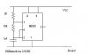
I've got so far on MultiSim as this:

The real C1 that I have is 0,9 nF, R3~106.3k so the frequency is theorically ~13.63 kHz (in reality, I think it will be less due to circuit losses/non idealities) and theorical maximum duty cycle LOW ~9.46%. In the schematics I'm using a 1uF capacitor because I can't synchronize the signals on the oscilloscopes (I started to use MultiSim less than a week ago).
Also, the PNP transistors I'm supposed to use are S9012 (Ic_max = 500 mA), LED pulses are generated to get a maximum 100 mA current value in a two LED series. I'm using PNP because all the complementary NPN I have (S9013) have lower hFE measurements (~300 vs ~220), still I can use either.
LEDs will be white so ~4.5V at 100mA are expected (very uncertain about this, it's just data collected from the web). I have very little clue about calculating R4 value. I read the PNP transistor should function in satured mode in order to dissipate very little power (Vec_Sat ~ 0.2V times 0.5A results in 100mW).
R5 value should be (Vsupply-2*VLED-VECsat)/.1=(12-2*4.5-0.2)/.1=28 Ohm, right?
Thank you.
I'm trying to build a circuit using a 555 as astable multivibrator to generate a square wave of frequency >= 10 kHz and duty cycle HIGH >=90% (duty cycle LOW <= 10%) in order to drive PNP BJT.
I've got so far on MultiSim as this:
The real C1 that I have is 0,9 nF, R3~106.3k so the frequency is theorically ~13.63 kHz (in reality, I think it will be less due to circuit losses/non idealities) and theorical maximum duty cycle LOW ~9.46%. In the schematics I'm using a 1uF capacitor because I can't synchronize the signals on the oscilloscopes (I started to use MultiSim less than a week ago).
Also, the PNP transistors I'm supposed to use are S9012 (Ic_max = 500 mA), LED pulses are generated to get a maximum 100 mA current value in a two LED series. I'm using PNP because all the complementary NPN I have (S9013) have lower hFE measurements (~300 vs ~220), still I can use either.
LEDs will be white so ~4.5V at 100mA are expected (very uncertain about this, it's just data collected from the web). I have very little clue about calculating R4 value. I read the PNP transistor should function in satured mode in order to dissipate very little power (Vec_Sat ~ 0.2V times 0.5A results in 100mW).
R5 value should be (Vsupply-2*VLED-VECsat)/.1=(12-2*4.5-0.2)/.1=28 Ohm, right?
Thank you.
Last edited:


")