Continue to Site

Welcome to our site!

Electro Tech is an online community (with over 170,000 members) who enjoy talking about and building electronic circuits, projects and gadgets. To participate you need to register. Registration is free. Click here to register now.

  • Welcome to our site! Electro Tech is an online community (with over 170,000 members) who enjoy talking about and building electronic circuits, projects and gadgets. To participate you need to register. Registration is free. Click here to register now.

Led / Phototransistor Question

Status
Not open for further replies.

Ken1

Member
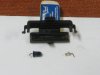
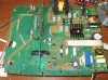
Hi, I know it's a long shot but has anyone seen a put together optoisolator unit like this? The left unit is an led and the right unit is a phototransistor. This is from a Gallagher MR2500 farm fencer. It's used to couple a sample of the high voltage pulses to a monitor circuit that lets the user know the output status of the fencer at a glance by flashing a green led if the output is ok or a red led if the output is low due to a leaky or shorted fence. The lead wires have rotted off due to moisture getting into the fencer and I am trying to repair the unit. The second photo is the fencer's circuit board. There are 2 of these optoisolator units as can be viewed.
 

Attachments

  • IMG_0118a.jpg
    IMG_0118a.jpg
    91.6 KB · Views: 156
  • IMG_0122a.jpg
    IMG_0122a.jpg
    678.3 KB · Views: 140
The plastic package looks custom to me, but it can be replaced with a piece of unshrunken shrink tubing, a dark soda straw, a small cardboard tube, a roll of paper, etc. Its only purpose is to keep the two parts in rough alignment and prevent light from one causing a false signal from the other.

If the other isolator is working, can you see if it is emitting visible light? That would be convenient. Also, how do you know that one of the isolators is defective?

ak
 
Hi, As I mentioned in my post the lead wires have rotted off both the led and phototransistor where they pass through the circuit board. This can be viewed in my first picture.
I was unable to open up the other unit without the lead wires breaking away from the board.
 
Hi, As I mentioned in my post the lead wires have rotted off both the led and phototransistor where they pass through the circuit board. This can be viewed in my first picture.
I was unable to open up the other unit without the lead wires breaking away from the board.
The two parts are widely available. If you are in the US, you can order the clear part (IR aemitter) and the dark part (phototransistor) from Digikey.com. They are under $1 each in quantities of one. RadioShack used to sell pairs like you show but, sadly, they are gone. Let us know where in the world you are, we can point you to a distributor. Otherwise look on eBay or amazon for emitter phototransistor for a pair.

Here is a box full of each for $10 with free prime shipping.
 
They wanted to increase the isolation voltage by a lot,

RadioShack used to sell pairs like you show but, sadly, they are gone.

Not quiet gone. More like DOS is dead. Long live DOS.

It should be easy to find a replacement pair, So,https://www.radioshack.com/products/radioshack-infrared-led-emitter-and-detector

This https://www.digikey.com/products/en...f=0&quantity=&ColumnSort=0&page=1&pageSize=25 is interesting

The flat is the polarity marking. The emitter likely goes on the HV side. Just noticed that the board is already marked.

You might consider conformal coating the board.
 
Last edited:
Hi, I am in Canada and Digikey does sell and ship to Canada. In fact I have purchased from them quite a few times in the past few years. Can you give me the Digikey part numbers or the links to the items?
 
Phototransistors


Ir emitters

There are a lot of different current ratings, voltage ratings and off-current (dark current) specifications. Those that I picked are general purpose/middle-of-the-Road specs with the higher end of voltage ratings and dark current.
 
You might be able to salvage the Led from a dead Tv/stereo remote control, be sure to get the polarity correct.
The tranny might be a bit more tricky to find.
Some expert use of a dremel and solder iron might get you some copper wire soldered to the stubby bits, you might be able to remove 1/16 or so of the plastic as the die/bond wire is fairly well buried.
 
Ok, I should mention that in the first picture the device on the left which is dark colored is the led and is bigger than the phototransistor which is clear and on the right.
 
Led is marked A=Anode(+) and K Cathode (-)

I think what we're trying to say without opening our "mouths" is see if you can select two parts and we can confirm if we think they are OK.

Known criterias
Size--->package---->lead spacing
LED
Photo-transistor
They should be IR and the same peak wavelength.
The receiving angle does not have to be wide.

I'd try the standard 20 mA nominal current LED, but I'd also select a lower sensitivity one as well if you can find one.

If you think it's just for monitoring, you might want to get a few visile leds in the 20 mA and 1 mA nominal to see if you can see a visible indication before putting the isolator together.
 
Last edited:
Status
Not open for further replies.

Latest threads

New Articles From Microcontroller Tips

Back
Top