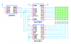
I'm sure I've seen somewhere an LED matrix with minimum pins. I was going to pick up one of these:
LED Matrix - LEDM88G
Which looks perfect for use with Nigel's tutorial. However I'm sure I've seen a few really good circuits that use less port pins by implementing row/column driver ICs.
I've also seen Mike's excellent PWM version of a similar thing, but I assume that would need all the pins too.
Can anybody suggest what other components/ICs I should buy at the same time so that I can try it?
")

