Continue to Site

Welcome to our site!

Electro Tech is an online community (with over 170,000 members) who enjoy talking about and building electronic circuits, projects and gadgets. To participate you need to register. Registration is free. Click here to register now.

  • Welcome to our site! Electro Tech is an online community (with over 170,000 members) who enjoy talking about and building electronic circuits, projects and gadgets. To participate you need to register. Registration is free. Click here to register now.

Led Matrix Mirroring Problem.

Status
Not open for further replies.

Gayan Soyza

Active Member
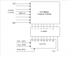
I’m making a 5X7 (5columns & 7 rows) matrix project. Rows driving from PORTB & columns driving from 74HC164.

I can scroll a letter nicely with a slow scrolling speed.

My problem is when I increase the speed of scrolling the letter is mirroring. Means some sort of shadow moving with the letter lines. So when scrolling speedily the letter is not sharp.

People who have experience with matrix designs may know this incident.

Code:
Table		addwf	PCL,F
		retlw	b'00000000'	;Letter 'A'
		retlw	b'00111111'
		retlw	b'01001001'
		retlw	b'01001001'
		retlw	b'01001001'
		retlw	b'00111111'
		retlw	b'10000000'	;80h

;**************************
;Main routine
;**************************

Start		call	CLRREG		;clear all RAM variables
		clrf	Pointer
		movlw	.100
		movwf	Scan_Count
		
Show_Loop	movf	Pointer,W
		call	Table
		movwf	Col5		;load to col 5	
		xorlw	80h		;end of letter??
		btfsc	STATUS,Z		
		goto	Start			
[COLOR="Red"]Loop1		call	Scan			
		decfsz	Scan_Count,F
		goto	Loop1	
		movlw	.100
		movwf	Scan_Count[/COLOR]		
		call	Shift				
		incf	Pointer,F
		goto	Show_Loop

;*************************
;simple multiplex routine
;*************************

Scan		bcf	PORTA,2		;reset SR-74HC164
		nop			;//
		nop			;//
		bsf	PORTA,2		;
		nop			
		bsf	PORTA,1		;enable data pin			
		movf	Col1,W		;1
		call	Clock_Pulse			
		bcf	PORTA,1		;disable data pin			
		movf	Col2,W		;2
		call	Clock_Pulse	
		movf	Col3,W		;3
		call	Clock_Pulse	
		movf	Col4,W		;4
		call	Clock_Pulse	
		movf	Col5,W		;5
		call	Clock_Pulse			
		return	

;**********************************
;Clock pulse routine to SR-74HC164
;**********************************

Clock_Pulse	movwf	Col_Data	;save column data
		clrf	PORTB
		goto	$+1
		goto	$+1
		goto	$+1
		goto	$+1
		goto	$+1												
		bsf	PORTA,0		;low to high transition
		nop				
		bcf	PORTA,0		;make low for next transition
		nop
		movf	Col_Data,W
		movwf	PORTB	
		goto	$+1
		goto	$+1
		return

;**************************************
;shift - moves one column data to left
;**************************************

Shift		movf	Col2,W	;2 to 1
		movwf	Col1		
		movf	Col3,W	;3 to 2
		movwf	Col2			
		movf	Col4,W	;4 to 3
		movwf	Col3		
		movf	Col5,W	;5 to 4
		movwf	Col4			
		return
 
Last edited:
Ya I have read them already.I think interrupt driven multiplexing routine is the only solution for my problem.

It must scan one column at a time without scanning the whole columns at once.

For now just only 5 columns may be it will end up with 128 columns.
 
Ya I have read them already.I think interrupt driven multiplexing routine is the only solution for my problem.

It must scan one column at a time without scanning the whole columns at once.

For now just only 5 columns may be it will end up with 128 columns.

I do not think so. It would be a lot easier to figure out if you posted all the code (in one listing) and the schematic.

Maybe some of this will help.

When driving multiplexed LEDs make sure the process (steps) of changing the IO to light the next set of LEDs does not cause unwanted LEDs to light when the change is in progress. As the scan speed increases this is more noticable.

Activate the display by first setting the uncommon bits then set (activate) the bit attached to the common.

I agree with others that the 74xx595 is an easier chip to work with for this sort of task. I like the latch and the ability to daisy chain.

3v0
 
I'll send him 74hc595 I gave up on 74hc164 and the 4015 I had thay work but the timing is be on me but them 74hc595 are like butter I have a old sign board that had 10 105 led modules that I been trying to put back in working order.
 
First of all I must thank all of you guys to be with me.

One thing to notice I cannot change the drivers to the 74HC595 it must do with 74HC164.My hardware is ready that’s why.

Here is the problem with a picture. So it will be more clear to you all what I’m talking about.

I’ll post my schematic + code as well.
 

Attachments

  • Mirroring Letter Problem.PNG
    Mirroring Letter Problem.PNG
    10.7 KB · Views: 482
Does this make any sense ?

To display each column

A: set portb (rows) such that all leds are off
B: setup the shift register to select the next column
C: set portb to select the leds you want on.
D: delay
C: goto A

If you skip step A you will have the mirror problem.

Assume you are sourcing the leds. Lets say you write 0x2F to portb to create the right leg of letter 'A'. You have these leds on and need to shift right to the next column where all of the leds should be off. But if you skip step A (turn off portb) the same LEDs will now be on in new column for a few machine cycles. They go off as soon as you update portb.
 
Last edited:
Hi 3V0 thanks for your input.I agree but in my "Clock_Pulse" routine I have done that.I have turn off LEDs & make one shift.So the shifting done with no data.

Here is the schematic.Its & 8X8 matrix I have used 5 from the 8 columns & took all 8 rows in the software.

I'm doing a column scan.
 

Attachments

  • 8X8 Matrix Display SCH.PNG
    8X8 Matrix Display SCH.PNG
    12.8 KB · Views: 472
With the aid of your last post I was able to read the code.
I only read asm when I have too. :)

If you can hook a 2 channel scope to two adjecent transistor outputs, maybe 2 and 3, look for overlap.

If not add more delay in the red code till the problem goes away. If that does not fix the problem I am wrong about it.

Code:
**********************************
;Clock pulse routine to SR-74HC164
;**********************************

Clock_Pulse	movwf	Col_Data	;save column data
		clrf	PORTB
[COLOR="Red"]		goto	$+1
		goto	$+1
		goto	$+1
		goto	$+1
		goto	$+1	[/COLOR]											
		bsf	PORTA,0		;low to high transition
		nop				
		bcf	PORTA,0		;make low for next transition
		nop
		movf	Col_Data,W
		movwf	PORTB	
		goto	$+1
		goto	$+1
		return

What clock speed are you running?
 
3v0 said:
If not add more delay in the red code till the problem goes away. If that does not fix the problem I am wrong about it.

Thats a very good point you have find out.When I got this problem I also doubt in that red color area.Earlier I added some few uS to that area.But never exceeded over 20uS.

Because I also see the column ON time is roughly 450uS & column OFF time(shifting time) is only 10uS.A big different :(

This time better add some more uS there & see.I'll tell the progress.

What clock speed are you running?

For 5-8 columns I use 4Mhz.
 
Last edited:
Hi 3V0 I have shifted my multiplex routine to the ISR & scans one column at a time.
You may wonder I have extended my columns to 32 oh my god…………..:D

I have fine tuned the “clock-pulse” routine to get a smooth scrolling.

I have added a flag bit to detect end of column scanning. After detecting that bit only I’m doing a “shift” otherwise the column values will be overlap.

Code:
;========================================
;Scans 32 columns one at a time 
;OSC=4MHz
;TMR0=78, Pre Scaller = 8
;Column registers starting with 30h-4Fh
;========================================

		org	0004h		 
		;
ISR_Enter	movwf   WT           	;save off current W register contents
		movf	STATUS,W        ;move status register into W register
		movwf	STAT
		movfw	PCLATH
		movwf	p_temp		;Save PCLATH 			
		
		;78(TMR0)X8(PS) =  624uS interrupts
		;624X32		=19968us
		;1/19968us	=   50Hz refresh rate

		movlw	.178		;
		movwf	TMR0		;load 78 TMR0			
		bcf	INTCON,T0IF			

Do_Col1		movf	Col_Counter,W	;	
		btfss	STATUS,Z
		goto	Do_Col_Scan
		incf	Col_Counter,F	;
		bsf	PORTA,1		;enable data pin only at first column

Do_Col_Scan	bcf	Enable,0	
		movf	Col_Counter,W
		addlw	2Fh		;
		movwf	FSR
		movf	INDF,W
		call	Clock_Pulse
		bcf	PORTA,1		;disable data pin
		incf	Col_Counter,F
		movf	Col_Counter,W	;check end of 32 columns?
		xorlw	.33		;//
		btfss	STATUS,Z	;//
		goto	ISR_Exit	;no,
		clrf	Col_Counter	;yes,clear column counter
		;
		[COLOR="Red"]bsf	Enable,0	;Flag bit confirms end of columns[/COLOR]
		goto	ISR_Exit
		;

ISR_Exit	movfw	p_temp
		movwf	PCLATH		;Restore PCLATH
		movf    STAT,W     	;retrieve copy of STATUS register
		movwf	STATUS          ;restore pre-isr STATUS register contents
		swapf   WT,F
		swapf   WT,W    	;restore pre-isr W register contents		
		retfie
 
Last edited:
One thing to notice that "bsf Enable,0" will set on every 20mS time.So the Shifting happening (scrolling) on every 20mS.Pretty fast.But when the column increases this is a normal speed.You have enough time to read the letter.

I tried to "slow the shifting speed" by counting two sets of "bsf Enable,0" that is 40ms.This is a nice speed but in this case that mirroring happening very badly.

Whats your comments?
 
That's cool hard work but a lot of fun doing it.I have been working on 1 with 12f683 and now using 74hc595 for the columns and trying to get one down too two pins for the rolls
 
That's cool hard work but a lot of fun doing it.I have been working on 1 with 12f683 and now using 74hc595 for the columns and trying to get one down too two pins for the rolls

Thats nice I also like to shift to 74hc595 in my next design & see how the timing goes in the clock routine.Its really hard to do with 74HC164.........I mean synchronizing with shifting speeds.
 
Last edited:
The led panels I'm using are 7x15 105 led's I think I'll use a 74hc164 for the roll's and 74hc595 for the columns I like the latch.But I say I'll use a 16f88 so I don't need the
74hc164
 
Last edited:
@Gayan,
I am glad to see you are making progress.

In theory on wants to keep ISRs as short as possible. Putting a 25mS delay loop in one is not good. Given that this uC does not have to do anything else you might get by with it.

This form of program would be more conventional. The code polls/checks the clocks overflow flag and uses no ISR.

Code:
start:
   setup clock to overflow as needed
   
Next:
   // other stuff
   if clock has not overflowed goto next 
   clear clock overflow bit
   all the actions you had in your ISR goes here
   goto Next

If you hand code you wanted to run independant of the clock you would put it where it says "other stuff".
The code does other stuff till the clock overflows. Then it services the clock.

If one wanted to use an ISR I would bust the led display code into parts. I have a good multitasking tutorial that shows how to do this.
 
Last edited:
Status
Not open for further replies.

Latest threads

New Articles From Microcontroller Tips

Back
Top