Continue to Site

Welcome to our site!

Electro Tech is an online community (with over 170,000 members) who enjoy talking about and building electronic circuits, projects and gadgets. To participate you need to register. Registration is free. Click here to register now.

  • Welcome to our site! Electro Tech is an online community (with over 170,000 members) who enjoy talking about and building electronic circuits, projects and gadgets. To participate you need to register. Registration is free. Click here to register now.

LED circuit question

Status
Not open for further replies.

lurkingdevil

New Member
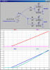
I have made a circuit here running leds.

**broken link removed**

I know this is not a good way of running them but what could be the possible issues?

All LEDs are same and the resistor is of appropriate value. The provided voltage is more than 3 times the forward voltage of a single led.

EDIT: I screwed up with +ve and ground. The right side is +ve.
 
Last edited:
Three things: get rid of the jumpers between the individual LEDs, use a separate resistor for the two LED branches, and as drawn, both ends of the branches are grounded :D
 
All LED's aren't identical. The ones that work with slightly lower voltage will steal all the current and the others will starve.
 
Three things: get rid of the jumpers between the individual LEDs, use a separate resistor for the two LED branches, and as drawn, both ends of the branches are grounded :D

Oh dang. I screwed up with the +ve and ground.

This is just a theoritical circuit, I am not actually doing this. I am doing this the way you said I should.

All LED's aren't identical. The ones that work with slightly lower voltage will steal all the current and the others will starve.

Please elaborate.
 
Last edited:
You would want the circuit to look a little like the attached. As mentioned your circuit has two ends grounded with no power source and drop the cross connections. Since you don't mention the forward voltage drops or current for the LEDs the attached is about as good as it gets :)

Ron
 

Attachments

  • String LEDs.jpg
    String LEDs.jpg
    18.3 KB · Views: 157
Last edited:
You would want the circuit to look a little like the attached. As mentioned your circuit has two ends grounded with no power source and drop the cross connections. Since you don't mention the forward voltage drops or current for the LEDs the attached is about as good as it gets :)

Ron

I just want to know what are the fundamental issues with my circuit. I have edited the OP, right side is +ve.
Like I said, all LEDs are same and the resistor is of appropriate value. The provided voltage is more than 3 times the forward voltage of a single led.
 
Last edited:
The fundamental issues are that all LEDs are not identical. Your corrected circuit will still have slightly different LED strings trying to hog the current.
 
Ron and Devil,

To see why each string of LEDs should have their own current-limiting resistor, look at this simulation which shows the effect of connecting individual LEDs (or strings of series-connected LEDs) in parallel. I purposely choose two different types of LEDs which have different forward voltage drops to connect in parallel. Note in the upper trace plane that when a single current-limiting resistor feeds paralleled LEDs, one LED I(D1) gets all of the current, while I(D2) gets none. In the lower panel, each LED has its own current-limiting resistor, and viola, now the both LEDS get a current dependent only on their own Vf and respective resistor.
 

Attachments

  • DF26a.png
    DF26a.png
    34.8 KB · Views: 155
Ron and Devil,

To see why each string of LEDs should have their own current-limiting resistor, look at this simulation which shows the effect of connecting individual LEDs (or strings of series-connected LEDs) in parallel. I purposely choose two different types of LEDs which have different forward voltage drops to connect in parallel. Note in the upper trace plane that when a single current-limiting resistor feeds paralleled LEDs, one LED I(D1) gets all of the current, while I(D2) gets none. In the lower panel, each LED has its own current-limiting resistor, and viola, now the both LEDS get a current dependent only on their own Vf and respective resistor.

Yeah, my bad Mike. All I did was quickly cleaned the OPs circuit up a little. I should have drawn it differently with added resistors.

Thanks
Ron
 
Read post number 3. "LEDs have slightly different voltage requirements." When one LED uses up the available current at slightly less voltage than the next LED needs to turn on, the second LED doesn't turn on. There is nothing in here about LEDs having zero resistance or having one of the two LEDs open.
 
Read post number 3. "LEDs have slightly different voltage requirements." When one LED uses up the available current at slightly less voltage than the next LED needs to turn on, the second LED doesn't turn on. There is nothing in here about LEDs having zero resistance or having one of the two LEDs open.

Thanks, that explains it.
In usual conditions though, both leds will turn on and one will be dimmer than normal and the other will be brighter than normal. Is that correct?
 
What would be the reason that the other led gets no current?
Is there zero resistance when one of the two led opens?

No, it has to do with the Forward voltage drop of the LED. Look at the attached Id vs Vf plot of two different LEDs called HPWA and HPWT (actually taken off a LumiLeds data sheet).

Suppose you connected the two in parallel, and used only one resistor that limits the current to 20mA. Now the sum of the two currents in the two LEDs must add to 20mA (Kirchoff current law). Look at the plot. With 20mA flowing through it, the forward voltage across a HPWA would be 1.95V. With 1.95V across the HPWT (Kirchoff voltage law), the forward current through it is only about 3mA, so instead of 20mA in the HPWA, the current is more like 17mA through the one, and 3mA through the other (iterate to your hearts content).

So, the bottom line is that with a single resistor, the LED currents are very asymmetrical, which would be corrected by having two higher value resistors..., one in series with each of the two LEDs, or if you have enough head room in the supply voltage, just put the two LEDs in series, and use just one resistor to set the current in both. Kirchoff guarantees that makes the two LED currents equal :D
 

Attachments

  • Lumi.png
    Lumi.png
    19.2 KB · Views: 123
Last edited:
A cheap Chinese flashlight (torch) has LEDs in parallel. The LEDs are not exactly the same so the one with the lowest forward voltage will be very bright with a current that is too high so it burns out soon. Then the next one burns out. Then the current is divided among fewer remaining LEDs which also burn out like a string of fire-crackers.

A good flashlight manufacturer measures and groups LEDs so they are exactly the same then the LEDs work fine in parallel.
 
Status
Not open for further replies.

Latest threads

New Articles From Microcontroller Tips

Back
Top