Continue to Site

Welcome to our site!

Electro Tech is an online community (with over 170,000 members) who enjoy talking about and building electronic circuits, projects and gadgets. To participate you need to register. Registration is free. Click here to register now.

  • Welcome to our site! Electro Tech is an online community (with over 170,000 members) who enjoy talking about and building electronic circuits, projects and gadgets. To participate you need to register. Registration is free. Click here to register now.

LED being dimmed or not showing any light Issues

Status
Not open for further replies.

justin126912

New Member
Hello there Friends,

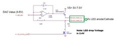
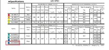
We are currently seeing some issues with a LED driver circuit. I am not sure about root cause because there are too many variables. During operation the LEDs are being dimmed or not light at all (After 2-3 months in operation ). Attached is the portion of the driver circuit for the LED, any ideas that would cause (Excessive electrical stress in the form of excessive current applied to the LED) the LED to be Dimmed or damaged. What would caused excessive current, beside a short we have too many LED being damage or go dim. Any help would be greatly appreciated

Thank You
WJ
 

Attachments

  • LED Spec1.jpg
    LED Spec1.jpg
    257.9 KB · Views: 314
  • LED Driver.jpg
    LED Driver.jpg
    53.6 KB · Views: 313
"Normally" you would put the led in the collector of Q10.

iu


In the above Ic = Vdrive / Remitter = Vdrive / 10 in this case.
So if you want max LED current to be Ix then
Remitter = Vdrivemax/ Ix (in amps). So for Imax = 50 mA
then Remitter = 5 / .05 = 100 ohms.

Then for shutoff use a small signal part to ground input of NI
OpAmp to power off. Use a R between Vdac and NINV input,
and use switch at junc of NINV input and R for disable operation.

What is supply you are using for LM324 ?

An LM324 has limited CM range input so you must observe that.
Or use a RRIO OpAmp.

Note many modern LEDs can glow at uA levels of current, and
LM324 when output driven low still at a few mV off ground. Just
be aware of that.

Here is a sim, you can see that the input CM range was violated of the LM324,
so power supply V would have to be raised from 5V, or use a RRIO part.

Note I used 3 diodes to represent RED LED as I had none in my simulator. To
get an ~ Vforward of a RED LED.
1640303571164.png


1640303511063.png


Herre I raised supply to 10V for the LM324, works fine.

1640303656604.png


Regards, Dana.
 
Last edited:
Here is sim with disable active to show current now in uA range.
I used a 2N7000, but lower Rdson parts would be better. Also
LM324 output when driven to its - supply, in this case ground, is still
~ 10 mV or so above ground, so that may have some consideration.
Again a RRIO part would be better.

1640304381097.png


Regards, Dana.
 
Status
Not open for further replies.

Latest threads

New Articles From Microcontroller Tips

Back
Top