Continue to Site

Welcome to our site!

Electro Tech is an online community (with over 170,000 members) who enjoy talking about and building electronic circuits, projects and gadgets. To participate you need to register. Registration is free. Click here to register now.

  • Welcome to our site! Electro Tech is an online community (with over 170,000 members) who enjoy talking about and building electronic circuits, projects and gadgets. To participate you need to register. Registration is free. Click here to register now.

LED 5 blinks and then a continuous light.

Status
Not open for further replies.
Der Strom's circuit can be simplified. The transistor is not necessary.

I have to go out now, so I'll post my suggestion later.
 
Last edited:
There are several problems with the circuit.

1. There is no "switch on reset".

2. The LED will only flash 4 times not 5.

3. The transistor is unnecessary, I would have used the Enable input to stop the count at 8.

I will now elaborate on these points:-

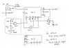
The 4O17 is a 5 stage Johnson counter, configured to operate as a Modulo 10 counter.

Having 5 stages, means that it has 2^5 = 32 possible states.

When a power is first applied, it will start in one of these states at random.

Therefore it needs some way to reset the counter to zero when the power is applied.

This is usually called a "switch on reset" circuit.

The LED will flash at states as 0, 2, 4 and 6.

The counter is prevented from counting beyond 8 so the LED will be on continuously (as intended).

It would be easier to use a 4 stage binary counter.

See the attachment.

The "switch on reset" circuit provides a brief pulse to reset the counter when power is applied.

The LED will flash at 0, 2, 4, 6, 8.

When it reaches 10, the Enable input goes low so the counting is stopped thus the LED is on permanently.
 

Attachments

  • Brake flasher.jpg
    Brake flasher.jpg
    202.7 KB · Views: 261
Thanks for your answer Len. Although i have already finished another design just yesterday as seen below. Sorry for the late answer.
 

Attachments

  • dsc00056tz.png
    dsc00056tz.png
    411.1 KB · Views: 256
Last edited by a moderator:
Hello. I have been assigned a task of designing a brake light with the following specifications:
1. The circuit shall start when given voltage (Obviously!)
2. It must be operational within 10-16V.
3. It must blink 5 times, and thereafter light continously.
4. The Blinking frequenzy must be approximately 5 Hz or similar frequencies appealing to the eye.
5. As the system is designed to replace current brake lights the only signal coming from outside the circuit is the 12V from the car.

I tried sending a 5 Hz test signal into a CD4017B decade counter. I thought i could then take every second output into an or gate made up of diodes a transistor and resistors. I thought this would give the five blinks and that connecting the last output leg to the clock inhibitor would then make a continous signal after the five blinks. The circuit would be resettable by coupling the voltage off. The final circuit would then be made up of an NE555 delievering the 5 Hz.

But the problem is that i have hooked up the decade counter as i mentioned on a test bench, but i am only getting a high low shift on the legs of the decade counter and not on the rest of the diodes that only show a low signal. I thought this would work. What am i doing wrong and could i possibly add some pulse width modulation to make the circuit more efficient?

I'm sorry for this long post but i don't have anywhere else to go to. So thanks in advance.

Simon.

OK, as per question you can take out put across 1 3 5 7 9 in sequence ....with help of OR Gate (just using few diodes) and than connect 10 output of 4017 to its enable pin.
the freq can be set by 555 chip to input clock of counter 4017 and 12V from braking can be given by light of your car.

Is that fine???
 
Status
Not open for further replies.

New Articles From Microcontroller Tips

Back
Top