Continue to Site

Welcome to our site!

Electro Tech is an online community (with over 170,000 members) who enjoy talking about and building electronic circuits, projects and gadgets. To participate you need to register. Registration is free. Click here to register now.

  • Welcome to our site! Electro Tech is an online community (with over 170,000 members) who enjoy talking about and building electronic circuits, projects and gadgets. To participate you need to register. Registration is free. Click here to register now.

LDR motion detector / op-amp cry for help

Status
Not open for further replies.

vidar

New Member
Hi all.

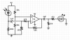
As a practical project to learn some of the trick of this trade I'm trying to build an LDR-based motion detector that will trigger some sort of action. (I'm planning to feed the result of this circuit to a 555 eventually, and go from there.) Almost all the circuits I've found on the use of an LDR depend directly on the light level, while I want to trigger on *changes* in light.

I have attached a rough draft that doesn't really work.

So, I'm having some problems. First and foremost, the changes in light level need to be very dramatic for the LED to react. I'm using an old LM741 for amplification, but the result isn't very satisfactory. I suspect the (admittedly somewhat arbitrarily chosen) resistor/capacitor values to be a big part of the reason for this. Can someone nudge me in the right direction on how to obtain a given gain on a signal? (I picked the 741 because it's mentioned extensively in literature. I have some others lying around, too, if that matters; HA17358, LM741CN, LM324N, UA741CN.)

And... Well, I think I'll just stop here and save the rest for later, unless I figure it out in the mean time. ;-)

Insight would be greatly appreciated. :)
 

Attachments

  • ldr-circuit.png
    ldr-circuit.png
    30.8 KB · Views: 4,483
You can increase the value of the 10k feedback resistor to increase the op amp gain.

The 470Ω and 100kΩ ohm resistors on the op amp input are not needed. Also the 741 can't put out that much current so you also eliminate the 470 resistor to the LED.

What is the DC voltage at the LDR output? It should be near 4.5V at normal ambient light. If not, adjust the 100kΩ resistor (to ground) value accordingly, or use a pot for this resistor.

The 1µF output capacitor means you will only see short pulses. If you want response to lower frequencies, use a 10 to 100µF cap, or even larger.

Do you want the LED to light on both an increase and decrease in light level. You circuit only turns on the LED when the sensed light is reduced. You could put the LED in a diode bridge if you want bipolar operation.
 
Thanks for your reply!

I ditched the two resistors you suggested and increased the feedback resistor to 1MΩ and that helped quite a bit. Still not quite where I want it to be, but it's definitely getting closer. :)

The voltage after the LDR varies a lot, actually. It's mounted inside a small tube for some directional control, so the voltage varies with what it's aimed at. I assume this might be a problem, since the negative end of the cap is at 4.5V. Will this chronic voltage difference across the cap reduce its effect?

Short pulses aren't a problem. The plan is to trigger a 555 or something when motion is detected, so a short pulse is fine. The LED is there mostly for debugging right now. And I will most likely add a rectifier bridge when the time comes, but for simplicity I'm leaving it out for now. :)
 
The negative end of what cap? Your schematic shows the positive end of the 1µF cap connected to the LDR. But since the voltage at the LDR can go above and below 4.5V (which is the operating point of the op amp input) the cap should be a non-polarized (ceramic) type, not a polarized type as shown.
 
Last edited:
Hi Vidar

I'm looking to do that same kind of thing — motion sensing with changing light levels on an LDR.

It's so good to find someone else working on the same thing, it suggests that I'm not barking mad.

How did this work out for you?

kr

Marcel
 
Your LDR and 100k resistor in series with it are a high resistance.
But your opamp is in an inverting circuit with an input resistance of only 470 ohms that kills the high resistance signal from the LDR.

Instead make the opamp in a non-inverting circuit then it has a high input resistance so it is very sensitive to the high resistance signal from the LDR.
 
Happy to say this has worked out nicely for me.

I've used two LDRs connected either side of an analog input pin on an Arduino (ultimately on an ATtiny85 programmed as an Arduino).

It was then easy to have the software monitor the analog input for fluctuations and easy to change the sensitivity too.

Much cheaper than PIR and it works well through a window. :)

[m]
 
That's good to hear. :) Can you give more info on the physical construction (photo?) or description of the distance or area it works over?
 
Last edited:
Status
Not open for further replies.

Latest threads

New Articles From Microcontroller Tips

Back
Top