Continue to Site

Welcome to our site!

Electro Tech is an online community (with over 170,000 members) who enjoy talking about and building electronic circuits, projects and gadgets. To participate you need to register. Registration is free. Click here to register now.

  • Welcome to our site! Electro Tech is an online community (with over 170,000 members) who enjoy talking about and building electronic circuits, projects and gadgets. To participate you need to register. Registration is free. Click here to register now.

LCD using pic controller

Status
Not open for further replies.
Those PDF's are really good.
I remember going through them when I was learning about LCD's.
They tought me everything i needed to know.
I would recomend them too.
I still refer back to to them.

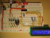
Get your self your breadboard, 44780 type LCD, bunch of resistors, and PIC. Go through those 2 PDF's and you'll be laughing.
 
can u pleas help me with any sample prog for interfacing lcd with pic..... sothat i can incorporate my own ideas, modifyin it....
 
As I said it is coded in assembler language.
Here is the schematic and the .ASM file.

This was one of my first program and has not been updated so please excuse the flaws of the program.

(The LCD is ran in 4bit mode, just so you know)

also, this is a calculator i used to work out the resistor values for the LM317:
LM317 Voltage Calculator
 

Attachments

  • Digital Voltage Selector B&W.jpg
    Digital Voltage Selector B&W.jpg
    279.8 KB · Views: 422
  • DVS.ASM
    38.1 KB · Views: 184
  • Bread Board.JPG
    Bread Board.JPG
    584.5 KB · Views: 443
  • Main Menu.JPG
    Main Menu.JPG
    140.5 KB · Views: 206
  • Menu Select 5v.JPG
    Menu Select 5v.JPG
    146.2 KB · Views: 229
  • Menu Select 9v.JPG
    Menu Select 9v.JPG
    143.2 KB · Views: 182
  • Menu Select 12v.JPG
    Menu Select 12v.JPG
    143.7 KB · Views: 234
  • Formula.jpg
    Formula.jpg
    31 KB · Views: 204
As I said it is coded in assembler language.
Here is the schematic and the .ASM file.

This was one of my first program and has not been updated so please excuse the flaws of the program.
...

Nice circuit Jake! Might I suggest with controlling the LM317 you could have used 2 transistors and a default resistor, instead of 3 transistors.

Besides being simpler it would have a safety advantage, as if the PIC fails or resets (any condition where PIC pins go open circuit) the voltage would be fixed at 12v. With your 3 transistor system the LM317 goes to max output voltage if the PIC is in reset or glitched as it's adj pin loses any reference to ground.
 
Status
Not open for further replies.

Latest threads

New Articles From Microcontroller Tips

Back
Top