Hey guys I am working on a digitally controlled 7.1 preamp just for myself as a bit of a hobby. So far I have drawn up the circuit for the front panel board which includes an LCD Display (HD44780), some LED's, some buttons and a rotary encoder. The rest of the circuit (which isn't drawn up yet) will include some Digital Volume Control IC's (PGA2320) from Texas Instruments, some relays for input switching, a D/A converter, and maybe an analogue 7.1 matrix decoder.
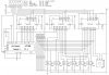
The LCD and LED's are controlled by two 74HC595 serial-parallel converters. The buttons and rotary encoder are read by a 74HC165 parallel-serial converter. The LCD backlight is controlled by a PWM pin. The LCD enable is connected directly to the PIC (in the rest of the circuit).
The data and clock pins of each '595 are connected to each other and then to the PIC rather than daisy-chaining them. This way I only have to shift one byte to update the LCD instead of 2. I imagine I will be updating the LCD more often than changing the LED's.
The load (/PL) pin of the '165 is connected straight to the PIC. The serial-out (Q7) from the '165 is connected to the '595 data pins through a resistor. This way I can change the corresponding pin on the PIC to an input to read the buttons, or an output to update the LCD/LED's.
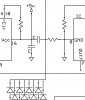
All of the buttons are OR'd together using small diodes for an interrupt-on-change function in order to know when to read the buttons. Is this the best way of doing this or should I poll the 74HC165?
Apart from that I am after any other advice you can give, I am still learning. Or are there any glaring mistakes perhaps? Maybe a way of doing something easier. Is the whole way of doing things OK?
Thanks in advance guys for any assistance you can give.
The LCD and LED's are controlled by two 74HC595 serial-parallel converters. The buttons and rotary encoder are read by a 74HC165 parallel-serial converter. The LCD backlight is controlled by a PWM pin. The LCD enable is connected directly to the PIC (in the rest of the circuit).
The data and clock pins of each '595 are connected to each other and then to the PIC rather than daisy-chaining them. This way I only have to shift one byte to update the LCD instead of 2. I imagine I will be updating the LCD more often than changing the LED's.
The load (/PL) pin of the '165 is connected straight to the PIC. The serial-out (Q7) from the '165 is connected to the '595 data pins through a resistor. This way I can change the corresponding pin on the PIC to an input to read the buttons, or an output to update the LCD/LED's.
All of the buttons are OR'd together using small diodes for an interrupt-on-change function in order to know when to read the buttons. Is this the best way of doing this or should I poll the 74HC165?
Apart from that I am after any other advice you can give, I am still learning. Or are there any glaring mistakes perhaps? Maybe a way of doing something easier. Is the whole way of doing things OK?
Thanks in advance guys for any assistance you can give.
Attachments
Last edited: