Hello, guys and girls!
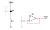
There is something I could use your help with. See, there is this project I am working on that requires me to detect a very weak optical signal (20-30 MHz, sine). So I was thinking of using a photodiode with a tuned LC circuit like the old day radio guys would and this is what I have come up with so far. Schematic is attached. The gray capacitors aren't really there. They are parasitic components for photodiode and opamp respectively.
From what I've read, for this purpose I need as big as Q as I can get. To do that for a parallel tank circuit the inductance has to be as big as possible and therefore capacitance as small as possible. So why not use parasitics from the photodiode and input of the op amp ?
This works like a charm in Multisim, but that's all theoretical and I'd like some more confidence in this idea before I order any parts.
Now, this is all theoretical as I have never made a single working LC circuit and odds are I could be missing something obvious. Like those capacitances doesn't really work like that. Or they aren't too stable. Or maybe the losses are too big for this to be considered.. I don't know. Any feedback would be appreciated.
Many thanks!
G.
Attachments
Last edited:
