Continue to Site

Welcome to our site!

Electro Tech is an online community (with over 170,000 members) who enjoy talking about and building electronic circuits, projects and gadgets. To participate you need to register. Registration is free. Click here to register now.

  • Welcome to our site! Electro Tech is an online community (with over 170,000 members) who enjoy talking about and building electronic circuits, projects and gadgets. To participate you need to register. Registration is free. Click here to register now.

LC Tank

Status
Not open for further replies.

Melfior_Ra

New Member
Hi everyone!

First of all please excuse my english.

I started to study by myself, as hobby, electronics. Now i am trying to figure out how oscillators work. The classic example, the LC tank, the one with a capacitor charged first by a dc power supply and then put in circuit with a inductor it is easy to understand. But in practice (Colpitts osc.) for me it's almost impossible to catch the trick.

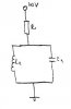
In the circuit attached, the capacitor is charging through the resistance. First, the courent that flows through capacitor is at maximum value, and as the cap. gets charged become smaller. The voltage across capacitor starts to rise. At some point a courent starts to flow through the inductor. The voltage rise and at some value the capacitor starts to discharge through the inductor. What is causing this discharge?

Thank you in advance!!
 

Attachments

  • untitled.JPG
    untitled.JPG
    4.5 KB · Views: 129
My understanding of this is purely practical.
The charge oscillates from inductor to capacitor, because they are opposite to each other, when the cap charges the inductor conducts and robs its charge, then the inductor has a voltage accross it and the cap robs it back again and the process repeats at a speed depending on the values of the coil/cap, the theory is that the oscillations would go on forever, only resitive and parasitic losses cause it to stop.
 
Last edited:
Think of it this way, per your description.

1. The capacitor, removed from the tank circuit, is charged (through the resistor, which is not absolutely necessary to the concept) to the value of the DC source
2. that cap is then removed from the DC source and connected to the inductor in parallel (as the schematic shows)
3. the cap immediately begins to discharge through the inductor, let's say, in a forward direction
4. this current from the cap causes a magnetic field to expand within the inductor, which reaches a maximum strength at some point.
5. as the cap's charge dissipates, the magnetic field of the inductor begins to collapse.
6. this collapsing field then induces a reverse current in the inductor which begins to re-charge the cap
7. when the collapsing magnetic field reaches a certain reduced value, the cap then, once again, discharges back through the inductor, again creating another magnetic field.
8. and so on and so on. In an ideal circuit, forever.

These are the oscillations referred to.

The process, however, (in the real world) can only repeat itself for so long without another injection of power (as Dr pepper noted) due to resistive and parasitic losses that dissipate the energy, thus stopping the oscillations.

An oscillating circuit, such as the Colpitts, is designed to "re-fresh" the tank circuit's power, thus maintaining the oscillations.
 
Last edited:
Hi melfior,

I suppose, you know that each frequency-dependent circuit can be viewed and described either in the time or in the frequency domain (thanks to the LAPLACE transformations).
Of course, you can try to explain the shown circuit in the time domain (as done up to now).
For designing and describing oscillator circuits it is, however, much easier to use the frequency domain for explaining the phenomena leading to self-sustained oscillations.
Remember: The classical oscillation condition from BARKHAUSEN (Loop gain=1 and loop phase=0 deg) is also formulated in the frequency domain.

For a parallel combination of L1 and C1 there is only one single frequency which allows a phase shift of 0 deg - that is the so called resonant frequency wo=1/SQRT(L1C1).
For this frequency the impedance approaches infinity - however, only in the ideal case with idealized quality factors for L1 and C1.
In practice, there will be a parallel loss resistor Rp.

As a consequence, the complete circuit as shown by you resembles at w=wo a pure resistive divider Rp/(R+Rp).

For example: Rp=2*R will lead to a voltage division ratio of 1/3. Now, if you connect this passive circuit in a closed-loop with an amplifier having a gain G=3 you have a working oscillator circuit.
This circuit meets the above mentioned criterion (BARKHAUSEN).
Hope it helps.
W.
 
Hi,

One way to get a good idea what is happening is to look at the voltage across both L and C and also the current through both L and through C. That's three waveforms to look at that have a couple of unique properties as to their phase shift.

The following diagram shows the voltage across both L and C and also the current through L and the current through C. Note that when the current in one element (L or C) is at the positive peak the other element current is at the negative peak. Also note that when both currents are zero, the voltage is at it's maximum peak.

Also, for this illustration all resistances (loss elements) have been removed to show how this works. To see what the resistances do all we have to do is imagine the waveforms getting smaller and smaller with time. They die faster with more loss and slower with less loss. Since there is no loss in the circuit being illustrated, the waves continue indefinitely. In a real life circuit they would die out eventually without the application of some more energy.

Also interesting is the energies in the cap and the inductor are being exchanged at twice the frequency of the currents and voltage, and that when the cap energy is max the inductor energy is zero, and when the inductor energy is max the cap energy is zero. The energies have the waveform of a sine squared shape, and are out of phase with each other by 180 degrees. The points where the cap energy is maximum is at the max voltage peak and min valley, and the inductor energy is max at the max inductor current peak and at the min inductor current valley (most negative). So even though the energy of the inductor appears 90 degrees out of phase with the voltage while the cap energy is in phase with the voltage, the energy transfer occurs at twice the frequency so a phase relationship isnt really possible unless this 2x frequency relationship is also noted. So the max energy of the cap appears at 90 degrees and 270 degrees, while the max energy of the inductor occurs at zero degrees and 180 degrees. This is a little contrary to the usual way of thinking of the LC in parallel because it is sometimes thought of as being in sync with the oscillation cycle but the energy exchange really occurs twice in one cycle.

ADDED: I decided another pic of the energies was a good idea so i added that below. Note the frequency of the energies compared to the frequency of the voltage.
 
Last edited:
Thank you all for your usefull explanations.
Now please correct me if i am wrong:
@MrAl
First when you push the switch, the cap acts as "wire" and through it flows a very large amount of current . In this time only a small amount of current flows through the inductor. Now comes the first question:
In your graph at t=0 you have maximum current through the capacitor, which I understood, 0 V at output, but a maximum negative current through the coil, which I dont understand why. At this time they dont act as current divider?
As time passes, the voltage rises across the capacitor and current through it drops. The current through inductor starts to raise and as oppose less resistance and the capacitor finds a path to discharge. When capacitor is fully discharged the inductor oppose the variation of current and generates a backward voltage which charge the cap on the opposite plate.
Again CORRECT ME IF I AM WRONG!!
Thank You!
 
Hi there Melfior,

Some good questions and you made some good points. It's my fault i should have mentioned that those waveforms are not starting at t=0 but some time after. In other words, the circuit was turned on a long time ago and we are just looking at the waveforms now. So t=0 on the graphs could really be hours after we actually turned it on, or even days, years, etc.
The reason for selecting this view rather than the actual startup was because this is really the most important view where we try to understand what is happening in the circuit after it is already running. It helps to understand better later if we decide to actually look at the true startup period.
The startup period includes an exponential part which isnt shown in the graphs in my previous post, but if you'd like to take a look at that next we could do that too. However i suggest you understand the circuit after it has been running for a while first and then start to think about the actual startup because the startup introduces some more complexities which after all only occur during the (usually) brief turn on period.
So take another look and see if you can understand what is happening and if so we'll proceed with the startup next if you like. In the startup time period we'll be looking at everything starting from zero energy in both elements. The circuit will eventually assume the waveforms shown in the graphs in my previous post.
 
........................................
In your graph at t=0 you have maximum current through the capacitor, which I understood, 0 V at output, but a maximum negative current through the coil, which I dont understand why. At this time they dont act as current divider?
.........................
To clarify, the current through the inductor and capacitor are always identical. They can't "divide" since there's no other place for the current to go in a series circuit. Currents are always the same in all parts of a series circuit.
 
To clarify, the current through the inductor and capacitor are always identical. They can't "divide" since there's no other place for the current to go in a series circuit. Currents are always the same in all parts of a series circuit.

Hi,

Yes good point, i should have shown the polarity of the current measurements in my graphs.
The polarity of the currents are both 'down' through the elements. That when the L and C are in parallel and drawn right next to each other with one lead down and the other lead up. Thus the current in one shows up as positive while the current in the other is negative. In reality both currents have the same phase.

I almost forgot to mention...
To supply energy to the circuit we can either use a current source or a voltage source provided there is some ESR in the capacitor. The current in the cap starts out high, but the current in the inductor starts out at zero.
But there are actually other ways to start this circuit too. We could start with 1v across the cap for example, or 1a through the inductor, or both, or use a source in parallel (the usual method). When we use the source in parallel the current starts out flowing down through both elements with the same polarity, but once we switch off the source the circuit can then begin to oscillate. If we use a current source we dont have to switch it off, but then we have some offset current in the inductor (inductor is a short circuit for DC). That's not a big deal but the waveforms will show up with the inductor current above zero for all or at least some of the time, but more time above zero then below zero than with no offset current. That's a little strange but it's just the DC current coming from the current source.
So the main idea here is that if we want to look at the startup waveforms as well as the normal running operation, we have to pick a starting method. For example, a common way to do this would be to use a voltage pulse to the circuit maybe in series with a good diode so that the voltage source has no effect after it goes to zero and lets the circuit oscillate normally.
Here is a short list of starting methods:
1. Initial voltage across the cap
2. Initial current through the inductor
3. Both 1 and 2 above
4. Voltage pulse with no diode
5. Voltage pulse with a diode
6. Constant current source
7. Current pulse
Note any starting method that involves a voltage source requires at least some series resistance in the capacitor.
Probably #6 is the easiest method to look at, but #1 isnt bad either.
 
Last edited:
Status
Not open for further replies.

Latest threads

New Articles From Microcontroller Tips

Back
Top