Continue to Site

Welcome to our site!

Electro Tech is an online community (with over 170,000 members) who enjoy talking about and building electronic circuits, projects and gadgets. To participate you need to register. Registration is free. Click here to register now.

  • Welcome to our site! Electro Tech is an online community (with over 170,000 members) who enjoy talking about and building electronic circuits, projects and gadgets. To participate you need to register. Registration is free. Click here to register now.

LC circuit inductance question for frequency calculation

Status
Not open for further replies.

qsiguy

Member
I have a high voltage LC circuit. It is powered by a 4-5kV transformer and I have an inductor and capacitive load in the circuit. My question is to calculate the resonant frequency of the circuit does the inductance of the HV transformer secondary powering the circuit need to be included in the calculation?

Typical values for one system with a single load is a 5 mH inductor, capacitive load is normally about 1.7-1.9 nF which produces a resonant frequency of about 1.4-1.6 kHz. These numbers calculate pretty closely to what I'd expect not figuring in the transformer secondary inductance which is probably about 3-6 H. I can confirm this value later if necessary for the discussion.

My goal of this discussion is to enable me to better estimate the proper inductance to put into the circuit with varying capacitive loads. As it is now, I have typical inductors that I know 'normally' work from 1 to 7 loads. Each load should be about 1.7-1.9 nF but occasionally I have a difficult time tuning a system du to load variances and I also want to test different load setups. It would be much nicer to be able to get better estimated results on paper without having to try everything on the bench under power. Not sure it's relevant but each load runs at approximately 500W. With all 7 loads installed the system runs at about 3500 watts.

Thanks for your input.
 
Hi.

You need to find out the output impedance of your transformer, more accurate. Assuming your load is directly coupled to your transformer, you need to take the transformer in the account too.
 
Assuming that the transformer secondary is directly connected to a parallel LC circuit, then the transformer secondary inductance would have to be taken in parallel with the inductance of the load. Since the transformer inductance is much higher than the load, it wouldn't likely have much effect on the circuit. However, the actual inductance of the transformer secondary, in operation, will likely be less than what you would measure under open circuit conditions. The admittance of the circuit on the primary side of the transformer is reflected into the secondary, which would have the effect of reducing the secondary inductance.
 
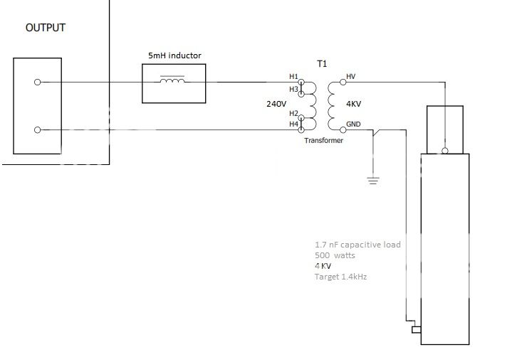
I explained the circuit wrong. Here is a sketch of it to clarify how it's setup. Inverter output though the inductor and HV transformer primary. HV transformer secondary just has the capacitive load on it. The load varies a little in capacitance and could have from 1-7 loads in parallel. The 5mH inductor gets changed based on the number of loads to try and maintain about 1.4kHz. At 7 loads the inductor gets changed to a 0.75mH. Ignoring the HV transformer in this circuit and plugging in the capacitance and inductance gets me a pretty close number based on what I've currently been doing, just want to refine my formula and the data points for more efficient engineering of various configurations.

Thanks for your comments.
 
You can transfer any impedance on one side of a transformer to an effective impedance on the other side of the transformer by multiplying by the square of the turns ratio, assuming an ideal transformer. The ideal transformer model may give you a useable ballpark number, but I'd be inclined to measure the transformer parameters and then model the whole thing in SPICE. If you have the means to measure phase angle, or true power, then it's quite easy to measure the parameters of your transformer, by doing an open circuit and a short circuit test.
https://en.wikipedia.org/wiki/Open-circuit_test
https://en.wikipedia.org/wiki/Short-circuit_test
Once you have these, a simulation will be straightforward.
 
Can the open and short tests be done with a power supply other than the one I am using for the actual circuit? The power inverter I use will not tolerate an open or a short on the load side or it will fault. Since the short test requires the test supply to be connected to the high voltage side and the low voltage side gets shorted I would assume you can use a "safer" lower voltage.
 
In the short circuit test, you must keep the voltage low enough that you don't exceed the maximum current rating. The best solution would probably be to use a sine wave signal generator running at the same frequency as your inverter, as long as it can put out enough current for the test. Otherwise, you may want to add an audio power amp into the circuit. I'd use the same signal generator for both the open and short circuit tests, so that you're dealing with sine waves and not a bunch of harmonics.

I just had a very brief look at the Wikipedia article before posting its link. It may be a bit short on details. However, there should be lots of info available on the net explaining these tests.
 
Status
Not open for further replies.

Latest threads

New Articles From Microcontroller Tips

Back
Top