Continue to Site

Welcome to our site!

Electro Tech is an online community (with over 170,000 members) who enjoy talking about and building electronic circuits, projects and gadgets. To participate you need to register. Registration is free. Click here to register now.

  • Welcome to our site! Electro Tech is an online community (with over 170,000 members) who enjoy talking about and building electronic circuits, projects and gadgets. To participate you need to register. Registration is free. Click here to register now.

Laser Burglar Alarm -- Need Help

Status
Not open for further replies.
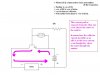
And also, do you know approximately how much voltage the laser (or any light source) has to provide to the photocell to turn the transistor on?

********

Well, its light really, i would say ordinary sunshine should push that sensor
to maximum conductivity.

Fortunately those little lasers have a pretty narrow beam, so the light
intensity is pretty high in the 'spot'.

At the other end however, most sensors dont start to respond until its
far from being dark, usually it needs to be better than even gloomy,
before a change is noticed.

Unless they are more sensitive than they used to be.
 
And the resistor just simply controls the current.

********

Well sort of.
In this case it sets the range of current that the transistor will operate within,
the cell controls the output current depending on the light.

The resistor is chosen, so that the base current is not too much for the cell to control,
and also that it has to be enough to turn on the transistor when the cell is dark.

Hope that makes sense ... the cell has direct control, the resistor sets the range.

*********

I hope the questions you face are not so in-depth.

John :)
 
Woah there, not at all.
I just thought you could do with a laugh.

You ask whatever questions you want,
i will try to answer as best i can
 
The concept of the emitter being in both the controling current path,
and also the output current path,
seems to need further clarification.

I will attempt to show how this occurs on the diagram.
back soon.

but i feel its a bit late where you are,
do you want to continue, or to leave it at that ?
 
Hope that makes sense ... the cell has direct control, the resistor sets the range.
Yeah ok, it makes, sense. Ty.

Woah there, not at all.
I just thought you could do with a laugh.
Ah ok, ty. Yeah, I definitely can do with a laugh. I'm thinking too hard.

Other than that, may you please just give brief explanations to the questions I had in the post with the 5 quotes.

I hope the questions you face are not so in-depth.
Yeah, me too. And also, my project is about alarms and I have 4 methods to describe (the laser method being one of them). So I'm probably also going to be asked about the other methods (i.e. ultrasonic, microwave, PIR) too. I think that since I chose the laser alarm method to be my model, I will probably be asked how it all works and like the general electron flow. If I mess up, he'll just continue asking.
 
but i feel its a bit late where you are,
do you want to continue, or to leave it at that ?
Well, it's only 1:20AM here. I think it's 6:20AM where you are so I don't know how you're managing to stay up and answer my questions. If you want/have to go, please do so. If not, I think that if you could give me brief one line explanations to those questions in the post with 5 of your quotes, I'll be good. It's not only the laser alarm that I'm going to be asked about and I have a math test to start studying for as well. Once again, I really appreciate your help. Thank you.
 
I don't know if John already covered this, but remember that current flow is described two ways: "conventional flow", where we refer to current flowing from the positive terminal of the battery to the negative terminal; and "electron flow", where we refer to the fact that the electrons actually flow from the negative to the positive terminal. From a practical standpoint it doesn't usually matter which you use as long as everybody in the conversation is using the same convention.

Whichever one I suggest you use in class, the teacher will prefer the other one. :)


Torben
 
Okay ...

heres the first part of the explanation concerning the operation of the
cell, and how the resistor sets the current range,
and the cell can alter the current in the emitter/base junction.
 

Attachments

  • final-circuit3.jpg
    final-circuit3.jpg
    53.4 KB · Views: 188
Hi Torben,

Yes, good point.
I have mentioned this already,
my solution is simply not to refer to direction at all,
simply to call it current flow.

As in an earlier post, i mentioned that surprisingly there is still an element of
difference of opinion over this silly issue.

If pressed, then clearly the issue should be mentioned,
but otherwise i have avoided scrupulously any mention of direction.

The explanations fortunately dont rely on any current direction.

Cheers, John :)
 
My preference is for 'electron flow' as i suspect are most people nowadays.
Hopefully it wont come up.

John :)
 
Having said that, my latest entry includes current direction !!

Just cant win can ya
 
Anonymous, you put that like you knew all about it.

.

did you know of this curious issue ??
 
I knew about that conventional current was from positive to negative and that electron flow was from negative to positive. But beyond that, I did not know. I did not know it was an issue either. I mean, they're two different things, right?
 
Fair enough.
I tend to stick to electron flow.
Just be aware, that sometimes people seem to argue for nothing.
 
Hey John, one last thing:

Briefly:
The transistor in this case is used as a current amplifying device,
the output current being controlled by the smaller base current.
The emitter is common to both current paths.
So the transistor is not used as a switching device anytime? I thought that this (a switch) was what we were using the transistor as.
And if you already answered it, whoops, and sorry.
 
my latest offering, and i wish i could set this out without arrows.
but never mind.

So long as you get the gist of it, i'm sure it will be fine.

Unless your tutor has a background in electronics,
it is unlikely he will have any particular opinion about current direction anyway.

So long as what you say makes sense, i'm hoping theres no reason for
direction to come up at all.

Just drawn this for you ,see what you think.

John :)
 

Attachments

  • final-circuit4.jpg
    final-circuit4.jpg
    48.2 KB · Views: 176
Ah ok. Sorry! Hopefully this is the last question: so the first diagram you had--is that current circulating when the light is on the photocell? Then the second diagram's current illustrating when the light is off the photocell?
 
Status
Not open for further replies.

New Articles From Microcontroller Tips

Back
Top