Continue to Site

Welcome to our site!

Electro Tech is an online community (with over 170,000 members) who enjoy talking about and building electronic circuits, projects and gadgets. To participate you need to register. Registration is free. Click here to register now.

  • Welcome to our site! Electro Tech is an online community (with over 170,000 members) who enjoy talking about and building electronic circuits, projects and gadgets. To participate you need to register. Registration is free. Click here to register now.

Laser Burglar Alarm -- Need Help

Status
Not open for further replies.
And of course you'll see me again! I'm just really busy now-a-days with school and such.
He didn't "destroy" anyone today. The key really is to know your topic and model down pact, I would say. Because if he catches you being unsure of something, it'll just go downhill for from there.
 
Last edited:
Hi,

Torben thought you might be a bit busy.
Nice to see you anyway.
If you do think of any questions you might get asked ...

And please let us know how it goes,
Cheers, John :)
 
Yeah, I'm just preparing them. Or rather thinking about of all of them so I can ask in one go. And yeah, of course, I'll let you know how it goes.
 
will it just be the tutor that asks a few questions,
or would it be anyone ?

(dunno anything about this sort of presentation)

John
 
Hi Anonymous,

Ive just noticed that i have put the resistor in the wrong place on that little diagram.
I'm very sorry about that, i hope that is not a problem with your stuff,
I feel a bit silly about that, i have re-positioned it on the diagram
to show where it really is.

John :(

*****
 

Attachments

  • final-circuit2.jpg
    final-circuit2.jpg
    26 KB · Views: 170
Thank goodness for that,
i would not want you to turn up with an error in your stuff.
 
Ok, I'm a little confused as to how everything works.

What exactly is a photocell? Wikipedia says that a photocell “is an electronic component whose resistance decreases with increasing incident light intensity. A photoresistor is made of a high resistance semiconductor. If light falling on the device is of high enough frequency, photons absorbed by the semiconductor give bound electrons enough energy to jump into the conduction band. The resulting free electron (and its hole partner) conduct electricity, thereby lowering resistance.”
So when light shines on it and gives it current, does the current flow from the emitter to the –ve of the 9V battery (i.e. the ground) and so the circuit stops (no current flows over to the siren)?
And then when the light is blocked, the 9V battery supplies current to the siren (b/c the +ve of the 9V is connected to the +ve of the siren)?
Why is the photocell connected to the emitter and the base? And not to somewhere else?
Why is there a connection between the collector and the -ve of the siren?
The resistor is supposed to resist current, isn't it? How does it turn the transistor on? Why is it connected from base to +ve of siren?

So basically, why is everything connected in the pattern that it is? I mean, somethings, I can make out.
 
easy ones first,

The resistor is supposed to resist current, isn't it? How does it turn the transistor on? Why is it connected from base to +ve of siren?

***

Well, its called a resistor because it has resistance.
It does resist current flow, but thats not its only function.
In this case its job is to control the current.

The degree of resistance is chosen to control the current, so that it suits what is wanted.
In this case it is to manage the transistor control current via the 'base',
such that the photo-cell can operate the transistor with the light from the laser.

Various values were tried, this value was suitable. Lower 'resistance' would mean more current,
Higher 'resistance' would mean less current.
The photo-cell works it satisfactorily using this value.

***

I'm trying to keep this in easy-to-understand terms,
I hope this comes across alright.

************

How does it turn the transistor on?
next post
 
How does it turn the transistor on?
************

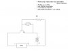
The resistor is positioned in the circuit to allow some current to flow through
the photo-cell and the base of the transistor.

At rest, with light on the cell, most of this current passes through the cell,
the base contributing very little towards the current through the resistor.

If the light is interrupted,
then the photo-cell changes and becomes less conductive, (higher resistance),
then the current through the resistor passes mainly through the base of the transistor,
and the photo-cell contributes very little towards the current through the resistor.

[i have tried to avoid reference to current direction, in some places there are still
disputes about how that should be expressed. I favour'electron flow', but i thought it
best to avoid it altogether, if you get asked about that it can be a headache]

Briefly:
The transistor in this case is used as a current amplifying device,
the output current being controlled by the smaller base current.
The emitter is common to both current paths.

[i doubt you would be expected to explain in great detail, but that should cover it]

****

Why is it connected from base to +ve of siren?
next post

Oh ok. Yeah, this came across perfectly. Thank you.

Thank You. (I do try)
 
Why is it connected from base to +ve of siren?

Thats the supply positive point.
it just happens to be the same connection.

The resistor goes from the base to the battery positive,
the siren also has a connection on the battery positive.

*********

What is a photo-cell ?

Ive looked at Wikipedia, redirected to photodetector, and yes its a bit technical.
They've tried to cover everything that could be a photo sensitive device.

For most purposes you only need to know about two basic types,
Ones that change resistance when light falls on them, like you have in this case,
Photo-resistive.
And ones that generate a little voltage when light falls on them, Photo-generative.
like camera retinas, and sunlight energy sources.

The type you have used in this unit is 'photo-resistive', it changes its resistance
when light (laser beam) hits it.

Briefly:
A photo cell is a device that responds to light,
how it responds depends on which type you choose for your purpose.
Photo-cell is a bit of a general term for many types.

[hope that covers it!]

***************

Why is the photocell connected to the emitter and the base? And not to somewhere else?
next post
 
Why is the photocell connected to the emitter and the base? And not to somewhere else?

Because the Emitter/base junction is the control point of the transistor.
The small current through this junction controls the output current.

[ The collector and the base both share the emitter in their current paths.
The base current and the collector current are separate currents,
but they share the emitter.
dont know how far you want to get into this ... ]

Briefly,
cos thats the control point.

***********

Why is there a connection between the collector and the -ve of the siren?
next post
 
Why is there a connection between the collector and the -ve of the siren?

*********

Connecting the siren straight across the battery, would make it sound, but to control it
we put the transistor in line with it.
In this case the transistor collector/emitter junction controls the current for the siren,
by being placed in the circuit between the siren neg and battery neg.

*********

Briefly:
Because the collector is the output connection of the transistor, and in this case it
feeds the negative connection on the siren.

****

So basically, why is everything connected in the pattern that it is? I mean, somethings, I can make out.
next post ...
 
So basically, why is everything connected in the pattern that it is? I mean, somethings, I can make out.

***************

well,
that arrangement is only one possible arrangement, using the transistors and stuff that you have.
That one was chosen for simplicity and basic straightforward construction, bearing in mind that
you would have to be able to answer some questions about it.

Other more involved circuits were mentioned, and at one stage i was wondering if single transistor
would be able to do it.

The basic concept is that the light affects the cell,
and the cell controls the transistor,
and the transistor controls the siren.

The cell would not have the strength to control the siren,
even if it did it would be "backwards",
that is low resistance (more conductive) when light falls upon it,
so the transistor 'reverses' the logic of the effect.

So theres two effects to cover,
one, the ABSENCE of light has to operate the siren,
two, the current needed by the siren is more than the cell can control. (in this case)

[hope that covers it]

John :)
 
Hope i havent just made it look more complicated than it is ....
 
No, you haven't made it complicated. I just need some clarification. Sorry for the relentless questions..

At rest, with light on the cell, most of this current passes through the cell, the base contributing very little towards the current through the resistor.
But where does it go then? Does it try to go to the siren but is not enough to make it ring?

If the light is interrupted, then the photo-cell changes and becomes less conductive, (higher resistance), then the current through the resistor passes mainly through the base of the transistor, and the photo-cell contributes very little towards the current through the resistor.
So then here, the resistor (which you said is controlling the current in this case) supplies enough current for the siren?

Briefly:
The transistor in this case is used as a current amplifying device,
the output current being controlled by the smaller base current.
The emitter is common to both current paths.
So the transistor is not used as a switching device anytime? I thought that this (a switch) was what we were using the transistor as...hmm...

[i doubt you would be expected to explain in great detail, but that should cover it]
Yeah, true. I just want to be able to understand everything properly so that I'll be able to relay it without hesitation.

The collector and the base both share the emitter in their current paths.
May you please explain (in the circuit) how? Like not detail, just in the circuit. The emitter and base I think I can see--is it by the photocell?


And also, do you know approximately how much voltage the laser (or any light source) has to provide to the photocell to turn the transistor on?

I'll read that last post about why everything is connected like that now.
 
heres a picture of my cat:
 

Attachments

  • Paranoid32.jpg
    Paranoid32.jpg
    315.3 KB · Views: 158
Status
Not open for further replies.

New Articles From Microcontroller Tips

Back
Top