Continue to Site

Welcome to our site!

Electro Tech is an online community (with over 170,000 members) who enjoy talking about and building electronic circuits, projects and gadgets. To participate you need to register. Registration is free. Click here to register now.

  • Welcome to our site! Electro Tech is an online community (with over 170,000 members) who enjoy talking about and building electronic circuits, projects and gadgets. To participate you need to register. Registration is free. Click here to register now.

Lab quality Power Supply

Status
Not open for further replies.

Beginner

New Member
Hello

I have just recently started a coarse on Basic Electronics. In the text book there is an "Optional Project" which is building a "Lab quality power supply"

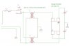
I have posted the schematic up to where I am in the book. Obviously there will be more to follow. I have tracked down all the parts up to the capacitors.

The 2 capacitors shown in the schematic are supposed to be 4400uF 50WVdc. My problem is the only capacitors I can find close to those specs are about $75 canadian each at Digikey. Can someone suggest an alternative to these or am I stuck paying the $150?


Thanks in advance!!
 

Attachments

  • supplyschematic.jpg
    supplyschematic.jpg
    55.9 KB · Views: 258
Last edited:
You can check here:

They have up to 3300uf at 50 volts but you can put 2 2200uf in parallel to get your4400.
 
The capacitance value is not critical. Anything from 4000 to 10,000uF will work (both the same value). The working voltage rating should be at least 40V. Look here for Capacitors.
 
The 2 capacitors shown in the schematic are supposed to be 4400uF 50WVdc.

That's an incredibly stupid value for them to have chosen - I've never even seen one 4400uF.

Use 4700uF which is a standard value - as previously suggested, it's in no way critical, and the bigger the better (and the tolerance is huge anyway). You may be able to find 4700uF at 50V, but 4700uF 63V is probably easier to find, and again it makes no real difference, with 63V been better than 50V.
 
Hi,

Apart from the above comments on the capacitor values, no one seems to mention the fact that the diagram shows two transformers - I hope you are not buying two of them as well.. ?? - unless you have need for such a large current ?

Also assume the posted schematic is just part of the whole power supply - and wonder what on earth they have done with the voltage regulators.

Would stongly suggest you search these forums and the web for a much better low cost diy psu design - they are cheap and easy

Think it might be worth you mentioning to this forum the name of the course / book you are using - makes me wonder if its any good ...


SOrry I should have mentioned the book. I know it is a an old book, but it still seems relevant today. the book is callled "The Tab Electronics guide to Understanding electricity and electronics".

He mentioned the use of 2 Transformers so we can have upto 1.5A so the unit can double as a battery charger.


Thanks all for the suggestions. I will look into them all!
 
I'm not sure I would call this a lab quality supply either, not by modern standards at least.
 
Actually Nigel, I had a couple bench supplies that we used in the lab at work that were just like that. Single Variac though for variable voltage. I'm not sure if you'd call them Lab supplies but they were used in one =) They were industrial lab supplies though, for doing Hull Cell testing on electro plating baths. The ripple was irrelevant for that.
 
Last edited:
There is more to the project then what I posted! The project follows set by step as the new lesson progress! Thats just how far I got so far!
 
Can only work with what I'm presented =)
 
I can read in between the lines pretty well, I can't read in between the schematics or code at all though =) Nigel and many of you other folks have seen some of these questions so many times or have real world experience to coincide with knowing exactly what the poster is trying to ask. I like things being a little more clear cut =)

There are so many threads here that get to 20+ posts before the original poster finally chimes in with "Oh you guys are all off base, what I meant was..." and then the entire previous weeks worth of postings from a few people are thrown completely out the window because the original poster wasn't specific.
 
Last edited:
There are so many threads here that get to 20+ posts before the original poster finally chimes in with "Oh you guys are all off base, what I meant was..." and then the entire previous weeks worth of postings from a few people are thrown completely out the window because the original poster wasn't specific.


Ahh but I was specific enough as you can see from the above posts! Thanks for all the advice guys. and sorrySceadwian I will try and add the hole schematic completely next trime!
 
Sorry if I come across hard Beginner. I am. I strive for ideals even I can't meet =)
 
NP problem bro. I am just trying to complete the projects in the book. Then later when I know more I will stray away from the book. Learn to make something even better!
 
When yer done with the book read it again cause then you'll know what you're doing =) You get more the 2nd time around with electronics books than you do with most anything else.
 
Has no one caught that the posted circuit diagram done by the OP in his first post is a dual voltage setup? Thus thats why it has two transformers.
With a pair of linear regulators he could have a full variable positive and negative rail 0-30 volt DC power supply.
Simple, but very useful!
 
Status
Not open for further replies.

Latest threads

New Articles From Microcontroller Tips

Back
Top