Grossel
Well-Known Member
Hi.
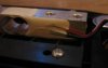
I have a kitchen weight where only the display is broken. So I have decided to find out how to make use of the sensor itself.
The censor have four wires conected to it, different colors. So I guess that it might work same way as hall censors, but doesn't know.
Plan is to use a breadboard and a circuit that can turn on a LED when the weight goes over a certain value. I can always adjust with a potmeter, so any curves isn't neccesary. Just to prove it works.
Question is: How to determine what is input and what is output wires from this weight censor?
The weight is not pilled apart so I haven't measured any resistance between wires yet.
")