Continue to Site

Welcome to our site!

Electro Tech is an online community (with over 170,000 members) who enjoy talking about and building electronic circuits, projects and gadgets. To participate you need to register. Registration is free. Click here to register now.

  • Welcome to our site! Electro Tech is an online community (with over 170,000 members) who enjoy talking about and building electronic circuits, projects and gadgets. To participate you need to register. Registration is free. Click here to register now.

Keypad help (floating voltages)

Status
Not open for further replies.

willsor

New Member
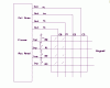
Hey everyone... I am building a keypad lock for a project using a PIC and one of those passive keypa with 8 pins,4 input 4 output. Each of the pins corresponds to a row of numbers on the 4 by 4 keypad, and the 4 output pins correspond to the numbers in that row..so putting a 1 into input pin 1 will make the 4 output pins correspond to 1,4,7,dot. Putting a 1 into input pin 2 now makes 4 output pins correspond to 2,5,8,0 etc... this then goes into the pic and that advances the programme etc.
The problem is, the keypad keeps advancing the program without you pressing a key, the voltage into the pic floats around 1-2.5v which I can't get rid of. I have tried putting it through a 4050 non inverting buffer but then the output of the buffer just floats too... it should be giving out a solid 0v or 5v,not 2.5v

Can anyone suggest what to do?
Sorry if it is hard to understand... believe me, its harder to explain ;)
Thanks
 
Last edited:
hi and welcome.
Whats the PIC type, are you using the internal weak pull ups.??
 
Hi, thanks for the swift reply.. apologies for that last post.. it was from my mobile and it didn't have much detail!

I am using a PICAXE28X.
I'm not sure what you mean by the weak internal pull ups, the keypad is all inside a plastic housing, so I can't get to it, but I'm pretty sure it's just a PCB.

I don't know the PIC has any internal pull ups, but if it does, I guess i'm using them
 
Last edited:
hi,
I dont use the Picaxe.
But on the PIC's I use they have internal 'weak' pull up resistors.

On the pins of the Picaxe that are used as inputs from the keypad, you need to have on each of the 4 pins a resistor from the pin to the +5V supply. The value of the resistors can be from approx 3.3K thru 10K, these will stop the pins from 'floating'.

If the output pins of the Picaxe to keypad are 'selected' high, you may have to connect the resistors as pulldown.

Post your Pixaxe program..
 
Last edited:
The pins are not in anyway connected to the 5v rail though, I'm not sure how to add that in, the only power the keypad recieves are the 5v signals from the PIC

EDIT EDIT: do you want a picture of the flowsheet, or the BASIC?
 
Last edited:
hi,
This is a typical app for a pad.

Is your program selecting the Rows or Cols as outputs, also is the selected Row/Column high or low.???

Code would do
 

Attachments

  • AAesp01.gif
    AAesp01.gif
    6.9 KB · Views: 231
'BASIC converted from Logicator flowsheet:
'F:\DO NOT DELETE\Flowsheet1.plf
'Converted on 24/6/2011 at 18:22:17


main:
write b0,0
let pins = 0 ' %00000000
let pins = 2 ' %00000010
label_476:
if pin0 = 1 then label_477 'Decision command
goto label_476

label_477:
if pin0 = 1 then label_477 'Decision command
gosub prc_ROW_1 'Do Procedure
gosub prc_ROW2 'Do Procedure
gosub prc_ROW3 'Do Procedure
gosub prc_ROW4 'Do Procedure
if b0 > 0 then label_412 'Compare command
gosub prc_SUCCESS 'Do Procedure
goto label_470

prc_SUCCESS:
let pins = 1 ' %00000001
pause 3000 'Wait command
return 'End

label_412: gosub prc_FAILURE 'Do Procedure
goto label_470

prc_FAILURE:
let pins = 4 ' %00000100
let pins = 6 ' %00000110
pause 3000 'Wait command
let pins = 0 ' %00000000
return 'End

prc_ROW4:
let pins = 130 ' %10000010
label_351:
if pin4 = 0 and pin5 = 0 and pin6 = 0 and pin7 = 0 then label_352 'Decision command
goto label_351

label_352:
if pin0 = 0 and pin1 = 0 and pin2 = 0 and pin3 = 0 and pin4 = 0 and pin5 = 0 and pin6 = 0 and pin7 = 0 then label_352 'Decision command
if pin7 = 1 then label_503 'Decision command
let b0 = b0 + 1 'Inc command
label_503: let pins = 10 ' %00001010
pause 500 'Wait command
let pins = 2 ' %00000010
return 'End

prc_ROW3:
let pins = 66 ' %01000010
label_337:
if pin4 = 0 and pin5 = 0 and pin6 = 0 and pin7 = 0 then label_338 'Decision command
goto label_337

label_338:
if pin4 = 0 and pin5 = 0 and pin6 = 0 and pin7 = 0 then label_338 'Decision command
if pin6 = 1 then label_509 'Decision command
let b0 = b0 + 1 'Inc command
label_509: let pins = 10 ' %00001010
pause 500 'Wait command
let pins = 2 ' %00000010
return 'End

prc_ROW2:
let pins = 34 ' %00100010
label_345:
if pin4 = 0 and pin5 = 0 and pin6 = 0 and pin7 = 0 then label_346 'Decision command
goto label_345

label_346:
if pin4 = 0 and pin5 = 0 and pin6 = 0 and pin7 = 0 then label_346 'Decision command
if pin4 = 1 then label_500 'Decision command
let b0 = b0 + 1 'Inc command
label_500: let pins = 10 ' %00001010
pause 500 'Wait command
let pins = 2 ' %00000010
return 'End

prc_ROW_1:
let pins = 18 ' %00010010
label_332:
if pin4 = 0 and pin5 = 0 and pin6 = 0 and pin7 = 0 then label_332 'Decision command
if pin6 = 1 then label_488 'Decision command
let b0 = b0 + 1 'Inc command
label_488: let pins = 10 ' %00001010
pause 500 'Wait command
let pins = 2 ' %00000010
return 'End

label_470: let pins = 0
stop

'Notes
'Variables A-H are shown as B0 to B7 in BASIC


I tried to put it in a collapseable thing, like a spoiler thing, but couldn't work out how D:

My keypad looks sort of like that one..

This is my circuit diagram
**broken link removed**

I made this table to help with explaining this keypad..
Basically read it like: when pin 5 has a 1, pin 1 will output 5v when key 1 is pressed... etc..
1 indicates high, blank indicates low.
**broken link removed**
 
Last edited:
hi,
The way I read your post, is that each column is pulled High in turn while the other Cols are low, and the Row pins tested for a high. [ if key pressed]

So that means you need pull down resistors on the Row inputs, say 2K2 or 4k7 resistor on each Row input pin to 0V.

So when no key pressed all Row pins are low.
A key press on a Col thats high will put a high on the correct Row pin.
 
Last edited:
Hi Eric
sounds good, will I still need the 4050 buffer chip?
Also I never really understood pull down resistors, if they can pull 1.5Vish down to 0, will a 5v signal be pulled down to 3V, or anything like that?
Thanks for taking the time to help me here :)


EDIT: do you mean this sort of setup? (red arrows just included to help clarity)
**broken link removed**
Note the significantly less amount of effort put into this diagram for no reason at all
 
Last edited:
if it helps, I just think of pull(up/down) as resistors that fill.or drain(pulldown) the energy on that pin,
 
sounds good, will I still need the 4050 buffer chip?
Also I never really understood pull down resistors, if they can pull 1.5Vish down to 0, will a 5v signal be pulled down to 3V, or anything like that?
Thanks for taking the time to help me here :)
EDIT: do you mean this sort of setup? (red arrows just included to help clarity)
hi,
Without pullup or pulldown resistors on Inputs that can be left 'unconnected' to an external source, the inputs are 'floating'.

This means the inputs can assume any state ie : '0' or '1'.
By placing your hand or objects, wiring etc, close to the pins, there can be sufficient induced voltage, to make the high impedance [CMOS]
inputs at a an indeterminate state.
So when your program reads the input pins it could be either '0' or '1'.
By connecting pulldown resistors the unconnected input pin will be held close to 0v, so the program will 'see' a '0' state.

For a Column that has been set to 5V by the program, will, if a key on that Column is closed, then Row pin will be pulled to +5V, which the program detects as a '1'.

Note: In some cases depending upon the sense the Column is set active, it could be that the unselected Cols are all high and the selected Col is pulled low.
In that case the Rows would have pullup resistors, so when a key is pressed the Row pin is pulled Low.

EDIT:
On many of the 'larger' PIC's on PORTB, there is an option in the configuration part of the program to enable 'weak' INTERNAL pullup resistors [IIRC about 50k.?].
So if pullups are needed the weak pullups are used.
 
Last edited:
I think I understand it now, the pull ups worked by the way, the outputs now sit nicely at 0 or 5v, not in between
Thanks very much for helping me so quickly :)
 
Status
Not open for further replies.

Latest threads

New Articles From Microcontroller Tips

Back
Top