Continue to Site

Welcome to our site!

Electro Tech is an online community (with over 170,000 members) who enjoy talking about and building electronic circuits, projects and gadgets. To participate you need to register. Registration is free. Click here to register now.

  • Welcome to our site! Electro Tech is an online community (with over 170,000 members) who enjoy talking about and building electronic circuits, projects and gadgets. To participate you need to register. Registration is free. Click here to register now.

KCX_BT_EMITTER Low cost bluetooth (BT) audio module

Sorry, I was in a rush when I posted the previous one.
To clarify, they are "senders" only, as far as I am aware, so you cannot use two of those for an audio link.

The self-contained modules typically have pairing buttons on them to connect with other devices; I've not used those exact ones but I have used similar things to set up an audio link when I was experimenting with some gear.
Do you know any Bluetooth modules that can be easily paired with each other and have audio transfer capabilities?
 
Hello all, I found this thread while trying to solve the problem of my kcx chip not connecting to a particular receiver. Thanks DrG and everyone else who contributed. I've learned a lot, and managed to speak to the chip via UART and a raspberry pi, but sadly while I can see the receiver, and command the chip to connect to it, it immediately disconnects again (I get the CONNECTED message, then a few moments later DISCONNECT). I have to confess, I'm drawing a blank. It seems like there might be some problem with the handshake between transmitter and receiver, but I'm hoping that enough clever people here have poked at the chip that someone might have a solution. Any ideas?
 
Do you know any Bluetooth modules that can be easily paired with each other and have audio transfer capabilities?
KES 205.00 18%OFF | Bluetooth 4.2 audio transmitter receiver board 3.7V~5V 10M Distance MP3 decoding wireless module Speakers diy 3.5mm for Arduino
 
Many thanks to everyone who has documented info on that KCX_BT_EMITTER board.

Just to let you know I created a small breakout board for it. Unfortunately I've given away all the spare boards I had but I have put the Gerber files in my GitHub for this project: https://github.com/RalphBacon/235_KCX_BT_EMITTER-Breakout-Board

If you would prefer the EasyEDA project files just let me know - it's all Open Source, after all.

One final point, is that this board performs better by a huge margin if connected to a small antenna (I used one from a spare ESP32). I now get a significantly better signal, no breakups at all. Quality of the audio signal is certainly good enough for my ESP32 Web Radio transmitting to a small BT speaker.

Regards
Ralph Bacon
www.youtube.com/ralphbacon
 
Has anyone worked with the KCX emitter v1.7? I can't find any documentation on it and am trying to get it to pair with...anything, in conjunction with a Gameboy Advance (which was proven successful on previous iterations - v1.1 I believe).

v1.7 seems to be using BT 5.3 from what I have found, and has a microswitch on the top of it, which I would assume would be for easy pairing, but I'm fairly new to this and can't seem to find any other forum than here that has worked with it.

edit: after looking at the transmitter again, it is a pair button. I'm thinking I'm not getting power to it properly. Gonna pull out the multimeter
 
Last edited:
Firstly, thanks to DrG and the other contributors to this topic. It is most informative and helpful!

I wonder if anyone here has had any success connecting KCX_BT_EMITTER to a Windows PC (so that the PC becomes a Bluetooth speaker)? My project requires this, but so far I have come up short.

With 'Bluetooth Audio Receiver' running, my phone connects for audio quite happily and I can play music through to the pc speakers. The KCX device will connect (only by using the AT+CONADD command). It registers as an Audio device called AC46_SDK. Trouble is, it is a hands-free mono connection, and there is no audio transmission takes place.

In case of this being a Microsoft issue, I have tried running with CSR Harmony, and also with BlueSoleil. The results are similar in all cases, that is - a connection can be made, but no audio is received.

Any ideas, tips, or suggestion for alternative modules welcomed.

Edit: I think I am on a wild goose chase with this quest. While the phone connection properties show "Advanced Audio Source" in the services list, the AC46_SDK and also a TX16 audio adapter (running in transmit mode) do not. Both of these list "Audio Sink", but not source. Apparently 'dumb' BT devices like headphones and speakers (and audio adapters) don't concern themselves with this stuff, and just work anyway...
 
Last edited:
I contacted SIQMA (where I ordered the part) and got a chinese PDF for version 1.7 of the emitter. I did my best at using Adobe Reader to recognize Simplified Chinese and used google translate to english. Some text wasn't recognized, however. I'm attaching both versions of the PDF
 

Attachments

  • KCX_BT_EMITTER english.pdf
    753.7 KB · Views: 1,309
  • KCX_BT_EMITTER.pdf
    2.5 MB · Views: 351
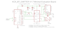
BT_EMITTER_V1.7 - correct documentation for AT-Commands available
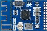
I have purchased a few of these from Aliexpress to develop a project.
The documentation I had was NOT for the 1.7 TX/RX model, and it was quite useless.
Kindly, the seller was able to send me the Chinese documentation, and through an online converter I managed to have something almost readable in Elnglish. I am sure you will find it to be just enough.
A few notes for the developers of circuits based on these modules.
1) I can assure you that when mounted "clean" on a PCB with some good XR7 or XR8 caps on +5V and GND, they are very quiet and there is no annoying noise typical of BT modules. I am using a 1uF and a 22uF in parallel. The secret is in the layout of the traces, but the modules themselves are very good even with quality (expensive!!!) SONY BT Heaphones.
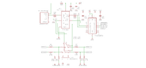
DGND (pin 2) is the one you should use for power, while AGND should be used for analog connections. For your PCB layout, derive these two lines directly from your power source as separate traces (best if NOT switching, or very well filtered for HF). Keep AGND for the module and the audio section (or Audio Jack) and do not share it with anything else that might introduce digital noise.
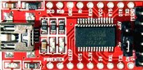
On the other hand, when you just connect the module to a RS232-TTL converter (FTDI Module for example), the sound quality is HORRIBLE and very demoralizing. Do not judge the module based on this. Do not use Arduino leads if not only to test the AT commands.
2) Between your TTL-serial port and the module, put at least 1 resistor (1K) on the RX input of the module. If you are designing a PCB, you might as well put one on the TX line. These will make sure you don't hear ANY noise which would otherwise be present (this I have noticed with MOST BT modules with a TTL serial line). The TTL levels here are 5V. So, if you drive the module from a 3V3 controller, you can use one of the many passive level translators available (ie from TI the TXS0104e)
3) On Windows you can use REALTERM to setup your com port, and then send the AT commands very easily, terminating each with +CR +LF. If everything works fine, you'll get your reply from the module. Also, at power up, if your port is configured correctly at 115200baud, you'll start receving a POWER_ON message and a few other chars. ANSI decoding works best in REALTERM to read your replies.
4) The 1.25mm connector is a bit challanging for some, but again, these modules should be mounted on a proper PCB so that you can use the correct Caps on the power lines. MAKE SURE the area around the BT antenna is clear on all sides if you want to have a decent connection
5) the module has a TX/RX jumper on board. Unfortunately it is not on the main connector because the module can be hot-switched from one mode to the other - All you have to do is put in in POWER_OFF mode with the appropriate AT command, change the jumper, and either press pair, or send a Low Level on the CONNECT line to wake up the module. With the connector at the bottom, the lower pad of the jumper is GND, and the upper pad is the TX(h) RX(l) input that can be connected to a GPIO of you controller
6) I have tested one module in RX mode (receiving from my phone) and connecting the audio lines to a second module in TX mode (connected to my good SONY heaphones), and I was IMPRESSED by the performance.

THE ONLY ISSUE HERE with these products are:
A) Availability in time
B) Certifications (are they available, and most of all... valid???
C) At these prices... are we sold top-quality modules that reflect the certifications, or are we getting rejects that will not pass scrutiny in the EU and USA?
That said... here are the docs I have; hope you can use them at best.
 

Attachments

  • BT GY19733-CN.zh-CN.en.pdf
    2.9 MB · Views: 395
  • BT GY19733-CN.pdf
    2.6 MB · Views: 224
KCX_BT_EMITTER V1.7 Sample schematic with Audio Switch.
The USB port is present to connect the module to a PC and become a "sound card". Note that power VBUS is only connected via R1 for level matching, but it is not meant to power the circuit.
The Module should be powered by a clean +5V. If your controller is 3V3 powered, IC1 provides level translation. (you might not need it)
Since this is a TX/RX module, you also need some sort of audio multiplexer (U$1) or you have to switch manually your source/destination.
R6,10,11,8 serve to adapt the audio levels at the module input (TX/!RX Low), while R7,9,12,13 do the same for the output lines (TX/!RX high). The values depend on your levels... they could all be left out.
R3 is important, R5 is optional; they reduce digital noise.
Your digital lines are
BTTXCONN to wake up the module after a power_off
BTTX/RX to select mode
RX and TX as serial lines (TTL 5V on the module, 3V3 at IC9) to the UART (notice they are UART refernced)
BTLINK returns the status of the module
 

Attachments

  • txrx.png
    txrx.png
    54 KB · Views: 369
This is a minimal Evaluation Board that can be built without a PCB (even if that would be recommended) to test the serial communication (AT+ Commands), the USB Sound interface, and the basic features of the KCX module.
Either or both Diodes can be used to power the BT module from USB. In case of a single power line, they can be removed completely. The shield to Gnd R/C snubber can also be skipped for simple testing.
Using CTS as an input and DTR, RTS as outputs that can be controlled by the FTDI module, we can switch mode TX/RX, apply a transition level to CONNECT and read back the status of the LINK line.
Note that setting DTR or RTS means bringing the level LOW, while clearing it brings the level HIGH.
So, set DTR will drive CONN LOW, and clear DTR will bring it back to HIGH causing a wake-up/Pair request.
Accordingly, set RTS will drive RX/TX LOW, equivalent to closing the jumper, meaning RX mode, while clear RTS will bring RX/TX HIGH, equivalent to opening the jumper and therefore requesting TX mode.

I have found 2 undocumented commands that produce a rather useless and confusing effect:
Since AT+BT_MODE? return the modality set by the jumper, I tried:
AT+BT_MODE=0 to set RX mode and
AT+BT_MODE=1 to set TX mode
The module actually accepts the commands and DOES the switch, but it immediately performs a init and reads the jumper, making the effort useless. Perhaps I am missing something here, and somebody finds a way to make this work. It would save us from connecting the TX/RX line to a physical GPIO. Mind you, you would still need an Audio Switch connected to A_L and A_R driven by a GPIO, so...
 

Attachments

  • KCX-TRX Minimal EVB.png
    KCX-TRX Minimal EVB.png
    37.8 KB · Views: 345
  • KCX-TXRX-V17.jpg
    KCX-TXRX-V17.jpg
    112.4 KB · Views: 313
  • INTERFACE FT232RL-USB-TO-TTL-Converter.jpg
    INTERFACE FT232RL-USB-TO-TTL-Converter.jpg
    29.4 KB · Views: 253
Last edited:
I am not into Bluetooth, but I was gifted a pair of earbuds and wanted to add Bluetooth to my desktop so I could listen to the SDR.
 
I am not into Bluetooth, but I was gifted a pair of earbuds and wanted to add Bluetooth to my desktop so I could listen to the SDR.
This chip would do what you need
Look at the schematic for the Simple Evaluation board above. If you want just basic functions, you won't even need the serial port - just leave the module in native TX mode. The Module will enter PC-Sound mode (channel=2) and become an out-sound port transmitting to your earbuds.
 
I asked the aliexpress store (where I bought them from) if these modules came with any certification, and I was told that the manufacturer has not applied for any. That is very unfortunate for serious projects that might use them. I would like to find out who actually makes these.
In the mean time, a costly but much more reliable source of BT modules is www.feasycom.com and the BT806A might be an interesting module. They can be bought from their website or from the feasycom aliexpress store.
 
I am not into Bluetooth, but I was gifted a pair of earbuds and wanted to add Bluetooth to my desktop so I could listen to the SDR.
Pretty much any generic USB bluetooth adapter will do that, most are plug-and-play with recent Windows versions and can usually auto-switch the audio to headphones when they are connected, then revert to speakers when disconnected.
 
Friends. I bought 3 kcx bt emitter v1.7 modules and they just keeping blinking red and I can't get it to pair to anything. On the online videos they made it seem automatic, but none used the v1.7...
You know what I might be doing wrong? Thanks!
 

Latest threads

New Articles From Microcontroller Tips

Back
Top