Continue to Site

Welcome to our site!

Electro Tech is an online community (with over 170,000 members) who enjoy talking about and building electronic circuits, projects and gadgets. To participate you need to register. Registration is free. Click here to register now.

  • Welcome to our site! Electro Tech is an online community (with over 170,000 members) who enjoy talking about and building electronic circuits, projects and gadgets. To participate you need to register. Registration is free. Click here to register now.

K8LH "Breadboard Buddy" LCD Interface

Status
Not open for further replies.

Mike - K8LH

Well-Known Member
Just wanted to pass along an untested idea for adding functionality to the original Myke Predko 2-pin LCD Interface design. Constructive criticism and comments are welcome.

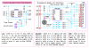
I'm trying to come up with a relatviely simple LCD+Buttons+Speaker device with a 2 or 3 pin interface to provide the basic functions I need when I use low pin count PIC devices on a breadboard. This would actually become the third device in a series of hobby "Breadboard Buddy" products I'm developing.

I hope to test the first circuit soon (below). If I can get that working then I think I would like to try connecting the SWX pin (switch matrix output) through a resistor to the 'DAT' pin and try to get all the same functionality with just a 2 pin 'DAT'/'CLK' interface.

I will pass along sample Assembler and BoostC routines in a subsequent post.

Kind regards, Mike
 

Attachments

  • Predko Mods v1.PNG
    Predko Mods v1.PNG
    74.7 KB · Views: 990
  • BB-LCD-A.PNG
    BB-LCD-A.PNG
    20.2 KB · Views: 615
Last edited:
That's a real cool ideal. There something about getting the most out of a 8 pin pic
like 12f683. I've been working on a logic probe with one. Use two pins for probes one to output a square wave. And the last two for some kind of display.
 
Hi Mike again a very busy PIC.I like that..............ahh thats the one you referred your new clock with tons of features :D

Today I'm going to buy a breadboard I have never used a one before :(

Mike I like this words.

"Breadboard Buddy" products
 
Last edited:
I keep meaning to make a simple PCB layout for the 2 wire LCD interface, with a header for the LCD to plug into and either a wire or pins to the breadboard (data and power).

Perhaps I'll get onto it tonight, it shouldn't take too long.
 
Hi Gayan,

I included the 12F683 in the drawing just to show how even a small 8 pin PIC can do something significant when some basic functions (LCD, keypad, speaker) are available through that simple Predko interface.

BTW, those latched output lines could be used to drive the columns (or rows) on a 3x4 or a 4x4 keypad too but that would require 3 or 4 input pins on the PIC.

Hi edeca,

Same here. I'm hoping to build this little interface soon. I'd like to build the whole thing into a nice little enclosure with tilt/swivel stand and just plug it into breadboard or other completed projects when needed.

Futz has some nice BoostC examples for driving the Predko 2-pin LCD interface on his web site.

Regards, Mike

-------------

Thought I'd post a sample subroutine for reading the switches and generating a "new press" beep. The DAT, CLK, and SWX pin defines are implied. The subroutine returns with switch A = swflags.0, switch B = swflags.1, etc..

Code:
;
;  unsigned char sample;        // switch work variable
;  unsigned char slatch = 0;    // switch state latch
;  unsigned char sflags = 0;    // switch flag bits (b3..b0)
;
;  void buttons()               // sample push button switches
;  { sample = 0;                //
;    DAT = 1;                   //
;    CLK = 1; CLK = 0;          // shift in a '1', QA==1
;    DAT = 0;                   //
;    if(SWX) sample.0 = 1;      // sample switch A
;    CLK = 1; CLK = 0;          // shift in a '0', QB==1
;    if(SWX) sample.1 = 1;      // sample switch B
;    CLK = 1; CLK = 0;          // shift in a '0', QC==1
;    if(SWX) sample.2 = 1;      // sample switch C
;    CLK = 1; CLK = 0;          // shift in a '0', QD==1
;    if(SWX) sample.3 = 1;      // sample switch D
;    CLK = 1; CLK = 0;          // shift in a '0', QE==1
;    CLK = 1; CLK = 0;          // shift in a '0', QF==1
;    CLK = 1; CLK = 0;          // shift in a '0', QG==1
;    sample ^= slatch;          // changes (press or release)
;    slatch ^= sample;          // update switch state latch
;    if(sample &= slatch)       // if any "new press" bits
;    { sflags ^= sample;        // update switch flag bits for Main
;      for(i = 0; i < 32; i++)  // do 32 msec 500 Hz new press beep
;      { DAT = ~DAT;            // toggle speaker using 1 msec
;        delay_ms(1);           // interval for 500 Hz tone
;      }                        //
;    }                          //
;    CLK = 1; CLK = 0;          // clear 74HC164 outputs
;  }
;
buttons                         ; 37 words
        clrf    sample          ;
        bsf     DAT             ; DAT = 1
        call    clock           ; shift in a '1', QA==1
        btfsc   SWX             ; switch A pressed? no, skip, else
        bsf     sample,0        ;
        call    clock           ; shift in a '0', QB==1
        btfsc   SWX             ; switch B pressed? no, skip, else
        bsf     sample,1        ;
        call    clock           ; shift in a '0', QC==1
        btfsc   SWX             ; switch C pressed? no, skip, else
        bsf     sample,2        ;
        call    clock           ; shift in a '0', QD==1
        btfsc   SWX             ; switch D pressed? no, skip, else
        bsf     sample,3        ;
        call    clock           ; shift in a '0'
        call    clock           ; shift in a '0'
        call    clock           ; shift in a '0', QG==1
        movf    sample,W        ;
        xorwf   slatch,W        ; changes (press or release)
        xorwf   slatch,F        ; update switch state latch
        andwf   slatch,W        ; any "new press" bits?
        bz      clock           ; no, branch, else
        xorwf   sflags,F        ; update switch flag bits for Main
        bsf     beep,4          ; beep = 32
beeper  movlw   1<<datpin       ;
        xorwf   datport,F       ;
        DelayCy(1*msecs-5)      ;
        decfsz  beep,F          ; done? yes, skip, else
        goto    beeper          ; loop
clock   bsf     CLK             ; toggle CLK line
        bcf     CLK             ;
        bcf     DAT             ; DAT = 0
        return                  ;
;
 
Last edited:
Why don't you just replace the logic chip with a small PIC, then you can make a standard protocol interface, like UART or I2C? It seems like an overly complicated interface when you could make the target 'smart' and handle everything including LCD functions on the peripherals side. Basically a serial LCD controller with buzzer and buttons.
 
This 74HC164 design just has a nice bang/buck ratio.
Really? How much would a PIC cost that you could offload these functions to? I don't work with PIC's, but I'm guessing $3 max. It doesn't seem like cost savings justifies the extra complexity and more work required by the master device.
 
Mark, you're probably right. Not that much more cost to go right to a PIC to provide a lot more capabilities. I still think it's kind of cool adding functionality to this simple 38 cent 74HC164 interface though.

Mike
 
I said all that, but I realize cost to functionality is not the same for a hobby project. I've done things the hard way plenty of times just because it's more interesting to do so.
 
I said all that, but I realize cost to functionality is not the same for a hobby project. I've done things the hard way plenty of times just because it's more interesting to do so.
That right you take the fun out of doing it the easy way. And getting a lot out of a 12f683 is always fun.
 
Pushing things further... you still have QH to play with. What if QH combined with the DAT (as done with the speaker) was used to disable/turn off the backlight?

That way you could appear to put the display to "sleep" (if desired).

Note the reverse logic however... which may not work if we have to continue to scan the keys while "asleep". (Though you may effectively get a PWM effect on the backlight, so "dim" vs "off"). Anyhow.. something to think about.
 
You can also look at my site and see how I did LCD interface with 74595 shift register and PIC SPI peripheral.
felis,

That's a very nice write up. You could easily modify the design to add a speaker and to use the latched outputs as column or row driver lines for a keypad.

Kind regards, Mike
 
I've been workin' on BoostC low level drivers and I think I've come up with a reasonably efficient set of instructions. I'll post equivalent assembly language drivers soon.

Mike

Code:
#define DAT portc.0             // DAT = RC0
#define CLK portc.1             // CLK = RC1
#define SWX portc.2             // SWX = RC2

/********************************************************************
 *                                                                  *
 *  low level breadboard buddy lcd drivers                          *
 *                                                                  *
 ********************************************************************/

 void clockout()                // clock out DAT pin bit
 { CLK = 1; CLK = 0; DAT = 0;   //
 }

 void putnyb(unsigned char data, bool rsbit)
 { DAT = 1;                     //
   clockout();                  // clock out lcd 'E' bit
   if(rsbit)  DAT = 1;          //
   clockout();                  // clock out lcd 'RS' bit
   if(data.3) DAT = 1;          //
   clockout();                  // clock out data b3 bit
   if(data.2) DAT = 1;          //
   clockout();                  // clock out data b2 bit
   if(data.1) DAT = 1;          //
   clockout();                  // clock out data b1 bit
   if(data.0) DAT = 1;          //
   clockout();                  // clock out data b0 bit
   DAT = 1; DAT = 0;            // strobe lcd 'E' input
   for(i = 0; i < 7; i++)       // clock out seven '0's
      clockout();               // clear 74HC164 outputs
 }

 void button()
 { unsigned char sample = 0;    //
   DAT = 1;                     //
   clockout();                  // latch QA == 1
   if(SWX) sample.0 = 1;        // sample switch A
   clockout();                  // latch QB == 1
   if(SWX) sample.1 = 1;        // sample switch B
   clockout();                  // latch QC == 1
   if(SWX) sample.2 = 1;        // sample switch C
   clockout();                  // latch QD == 1
   if(SWX) sample.3 = 1;        // sample switch D
   clockout();                  // latch QE == 1
   clockout();                  // latch QF == 1
   clockout();                  // latch QG == 1, spkr enable
   sample ^= swlatch;           // changes (press or release)
   swlatch ^= sample;           // update switch state latch
   if(sample &= swlatch)        // if any "new press" bits
   { swflags ^= sample;         // update switch flag bits
     for(i = 0; i < 32; i++)    // 32 msec "new press" beep
     { DAT ^= 1;                // toggle speaker
       delay_ms(1);             // interval for 500 Hz tone
     }                          //
   }                            //
   clockout();                  // clear 74HC164 outputs
 }                              //
 
Status
Not open for further replies.

Latest threads

New Articles From Microcontroller Tips

Back
Top