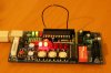
Can you explain how you work out from the schematic? I've obviously got that bit wrong and it would be good to know why
")
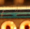
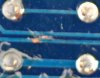
However.. the fact that I get virtually no resistance suggests that there might be a short somewhere. It could be where I think there is a fault on the PCB, I'll try and get a picture.

")
 hm: scale, 0 on all other scales. So our readings are different, any thoughts Bill?