MrDEB
Well-Known Member
I think I am stupid or something
I connected the junebug to the usb port
have dip switches 1,2,3 =on all others off
I get a yellow and green led light on=power and target power
the 3rd red led (row of 6)(from the left) is only slightly on, very dim
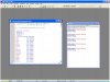
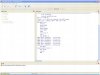
got mplab running but now what??
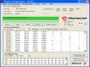
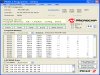
get pickit2 not dected then it says ready?? see screen shot
how do I see the leds blinking back and forth etc? or do the hello world thingy
missing something in the directions or ??
I connected the junebug to the usb port
have dip switches 1,2,3 =on all others off
I get a yellow and green led light on=power and target power
the 3rd red led (row of 6)(from the left) is only slightly on, very dim
got mplab running but now what??
get pickit2 not dected then it says ready?? see screen shot
how do I see the leds blinking back and forth etc? or do the hello world thingy
missing something in the directions or ??