Continue to Site

Welcome to our site!

Electro Tech is an online community (with over 170,000 members) who enjoy talking about and building electronic circuits, projects and gadgets. To participate you need to register. Registration is free. Click here to register now.

  • Welcome to our site! Electro Tech is an online community (with over 170,000 members) who enjoy talking about and building electronic circuits, projects and gadgets. To participate you need to register. Registration is free. Click here to register now.

Junebug help??

Status
Not open for further replies.
saving / making a module

why do some modules I am able to edit but others, in order to edit I have to copy n paste into a new file, edit then save again.
I have a file that I saved but I get file unable to open
using the swordfish compiler
 
timer code that works as planned

after getting in bed last nite it dawned on me how to alter the code to get just the 20 min delay then a short high.
have to change the 3 min delay to 20 min but it should work.
question= TOGGLE does go high then low (or visa versa depending on state of port??
Code:
Device = 18F1320
Clock = 8
Config OSC = INTIO2
Config MCLRE = Off
Include "INTOSC8.bas"           // set OSO
Include "Utils.bas"
Include "delaytimer.bas"


SetAllDigital
 TRISb =%00000000
 PORTb =%00000000
 Output (PORTB.1)
 While true
    //High (PORTB.1)
    
    longmindelay
     high(PORTB.1)
     delayms(30)
   
    Low (PORTB.1)
    //Longdelay
   
 Wend
 
to interject a C18 newb question:
I know that this

Code:
TRISb =%00000000
PORTb =%00000000

sets all of B as outputs, then sets them all low.
But what does this do?

Code:
Output (PORTB.1)

Code:
high(PORTB.1)
     delayms(30) //I understand this command
   
    Low (PORTB.1)

I gather that those are a way in C18 of setting ports high and low. But are they adjusting port b pin 1? or is the meaning something else?

And if you were to use the suffix "bits" when reffering to a port, would it work, and what would the syntax be?
 
Last edited:
Hi Triode,

They are using Swordfish Basic in this thread and so the commands you posted are not C18 commands. However, to answer your questions (in a C18 kinda way),

TRISB=0b00000000; sets all port B pins to output.
PORTB=0b00000000; sets them all low.

Output(PORTB.1) isn't C18 but I would guess the function OUTPUT would set the pin to output and would be the same as (in C18) TRISBbits.TRISB1=0; or TRISB&=0b11111101;. It may also set the relevant pin high.

The use of the suffix bits just allows you to set/clear or test an individual bit of a variable.

If you have a Junebug then I have posted a couple of examples in C18 that work with it.

Mike.
 
Last edited:
TRIODE Mrdeb using swordfish not C18 Mike you got back before me lol
 
Last edited:
Mr DEB,

The modules that you can't edit are system modules and you really shouldn't need to modify them. If you have to modify them then you are doing something wrong.

Mike.
 
I've moved this reply to the C18 thread, since it is more C18 related than junebug related.
 
Last edited:
Yes, you got most of that right. The OR-Equals is simply |= and not ||=. However, this is commonly known as thread hijacking and so we shouldn't discuss this further on this thread. However, feel free to start a new one with any other question.

Mike.
 
My apoligies, I felt this was on the line between thread jacking and creating duplicate threads, as my questions are for junebug use. But they are more specifically C18 related, and a thread for that would be usefull.
 
my code to date w/ lots of mistakes??

the code is several snippets compiled into one but be80be was concerned about code flow.
I rearanged but is it right??
I need to recheck all the code snippets (dip switch read in particular, might take it out and use for changing the timing interval.
Code:
// your main code would look like this
 Device = 18F1320
Clock = 8 // 8MHz clock
Config OSC = INTIO2, WDT = OFF, LVP = OFF
Dim day As Byte
Dim nite As Byte
Dim light As Byte
Dim checkPIR As Byte
Dim PlaySound As Byte
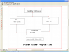

While true 
      If day = light Then PlaySound 
      ElseIf day = nite Then checkPIR 
      EndIf
      If checkPIR = true Then PlaySound
      EndIf
//Wend

//###########################
 //CHECK FOR DAYLIGHT OR DARK
//############################

//Device = 18f1320
//Clock = 8
Config OSC = INTIO2, WDT = OFF, LVP = OFF
Include "Utils.bas"
Dim but As PORTB.0
Dim led As PORTA.0
SetAllDigital      //set digital so you can read RB0 or it will always read low
TRISA =%00000000  // if your using the junebug This is fool proof to get a led to lite
PORTA =%00000000  // Set's it all low
TRISB =%00000001  // Set's inputs and outputs 
PORTB =%00000000   // Set's it all low
INTCON2.7=0        // sets wpu on portb turns on pullups on PORTB
OSCCON = $72            // 8 MHz clock
While true              // this loops it so it keeps checking 
If day = nite Then checkPIR // enables PIR                
    DelayMS(10)       // small debounce delay
ElseIf day = light Then Timer.Initialize  // triggers on timer
   led =1                 // Turns on led?????????
   DelayMS(10)       // small debounce delay
EndIf                     // closes your IF THEN statements 
Wend

End

End
//#################
//PIR ENABLE
//##############
  
If PORTB.1=0 Then PlaySound //if night then PIR is enabled
For i = 1 To 200 //play 20 tones
    Tone=Rand(5) //each tone is random frequency
DelayMS(Speed) //and for 1.00 seconds
Next //end for loop
Else //otherwise
     Tone=5 //silence
     i=Rand(255) //make rand more random
     
EndIf //end if condition
Wend //end of while loop
Wend
//##########################
      
     // then just make three functions One for day and night
     // One for PlaySound
     // One for checkPIR
//#######################
//TIMER ROUTINE
//########################

// 18F1320@ 8MHz - they are just used here for clarity...
//Device = 18F1320
//Clock = 8
while Timer.Initialize then //starts timer loop
//Device = 18F1320
//Clock = 8
Config OSC = INTIO2
Config MCLRE = Off
Include "INTOSC8.bas"           // set OSO
Include "Utils.bas"
Include "delaytimer.bas"


SetAllDigital
 TRISB =%00000000
 PORTB =%00000000
 Output (PORTB.1)
 While true
    //High (PORTB.1)   if daylight this timer runs
                       //and triggers PLAYSOUND 
    
    longmindelay
     High(PORTB.1)
     DelayMS(30)
   
    Low (PORTB.1)
    //Longdelay
   
 Wend
 /////end timer routine
 Wend// your main code would look like this
      
 
//#####################
//main code starts here
//######################

       OSCCON = $72            //select 8MHz internal clock
       NOT_RBPU=0              //WPUs on port B
       ADCON1=$7f              //all digital
       TRISB.0=0               //make output
       PORTB.0=1 //makes pin 8 high for dip switches
       T1CON = %10000001       //pre=1
       T1CON = %10000001 //pre=1
       Tone=5 //no sound please
       TMR1IE=1 //enable timer 1 interrupt
       TRISA=%10111110         //A0 & 6 output?? junebug code??
PORTA.7=1

While (true)
    Toggle(PORTA.0)
    DelayMS(200)
    Wend
End

//-------------------
//READ DIP SWITCHES
//-------------------

Enable(MyInt) //set interrupt going
SpeakerTris=0 //Setup Port
Seed=$12345678 //seed random number
        TRISA =%00001111          //sets your inputs on porta 
While(TRUE) //repeat forever

    If dip1=1 Then //dip1 pin 1   DIP SWITCH READ
       Speed=25
    EndIf
    
    If dip2=1 Then // dip 2 pin 2
       Speed=50 
    EndIf
    
    If dip3=1 Then //dip3 pin 6
       Speed=75
    EndIf                       // DIP SWITCH READ^
    
    If dip4=1 Then //dip4 pin 
       Speed=Rand(10)*15+15    //Speed = 25 to 250 random select speed
       
    EndIf
//##################     
// PLAY SOUND ROUTINE
//#####################
     
    // Device = 18F1320
//Clock = 8 // 8MHz clock
//Config OSC = INTIO2, WDT = OFF, LVP = OFF
if  PlaySound Then
Dim NOT_RBPU As INTCON2.7
Dim TMR1IE As PIE1.0
Dim TMR1IF As PIR1.0
Dim TMR1 As TMR1L.AsWord
Dim Speaker As PORTB.3
Dim SpeakerTris As TRISB.3

Dim Amp As PORTB.1 // turns on amp power
Dim AmpTris As TRISB.1//turns on amp pin 9
Dim Speed As Word
Dim dip1 As PORTA.0

Dim dip2 As PORTA.1

Dim dip3 As PORTA.2

Dim dip4 As PORTA.3

Dim dipRD As PORTB.0

//global variables
Dim Seed As LongWord, Tone As Byte
Dim i As Byte

//half period delays = clock speed divided by 2*frequency
Const Tones(18) As Word = (2000000/12000,2000000/10000,2000000/8000,2000000/6000,2000000/4000,1000,
2000000/12000,2000000/10000,2000000/8000,2000000/6000,2000000/4000,1000,2000000/12000,2000000/10000,2000000/8000,2000000/6000,2000000/4000,1000)

//################
//interrupt routine
//#################

Interrupt MyInt()
          T1CON.0=0 //stop timer
          TMR1=-Tones(Tone) //reset period
          T1CON.0=1 //restart timer
If Tone=5 Then //if silence
   Speaker=0 //speaker off
Else //otherwise
Toggle(Speaker) //make sound

EndIf
TMR1IF=0 //clear interrupt flag
End Interrupt

Function Rand(Range As Byte) As Byte
Dim i As Byte, feed As Bit, temp As Word
For i = 0 To 7 //generate 8 bits
    Feed = Seed.30 Xor Seed.27 //make new bit
    Seed=Seed*2+Feed //shift seed left and add new bit
Next
    Temp=(Seed And 255) * Range //change Rand from 0 to 255
    Rand = Temp/256 //to 0 to (Range-1)
End Function
 

Attachments

  • Capture6-27-2009-6.13.12 AM.png
    Capture6-27-2009-6.13.12 AM.png
    77.6 KB · Views: 305
I started getting an error that the 18F1320 wasn't detected, I was using MPLAB at the time and working with C18, after unplugging it and replugging it, then trying disconnecting it and pulling/reinserting the chips, it still had the issue. I happened to have some 18F1320's on hand, so I disconnected the peripherals incase they had caused the damage, and I put in a new 1320, It detected, and I programmed it once, then it quit working. I realize it may be my code causing the problem, but I don't want to risk breaking my last 1320 by switching again to try it with code that is known safe. If my code is what was locking up these chips somehow, or damaging them, where do I start diagnosing that to confirm the issue, or trying to repair it? What possible ways can a Pic be stuck so it wont detect, is it just burnt out?

edit, btw I can post my code later, the last change before this issue started is that I added a part to activate timer1 and its interrupt. I set it to non-synchronized, prescaler = 1, ocilator on, timer active. I know more detail would be good, but my code isnt on this computer.
 
Last edited:
Use the PICkit2 2.61 software to erase the part.

Are you using MCLR as an input? That can cause the 18F1320 on the Junebug to appear dead as for that you need to use VPP before VDD, that feature is only available on the ICD connector.
 
I had to force erase some 18f1320 just force. You may have to do it two times.
Chips always worked fine after.

What caused it was not setting the configure right in C18 and I used a hex for 16f88 and locked one up lol
 
Last edited:
I'll try erasing it like you suggest, I may have set MCLR as an input, But impretty sure I only set RB3 and RB0 to inputs, though it is possible that one of those are MCLR, I'll have a look at the datasheet.
 
It sounds like you have enabled the timer1 oscillator. Doing so makes the part unresponsive as the oscillator and the debugger share the same pins. The only way I found to get around this was to use a new chip so MPLAB recognizes it and then hot swap it with the unresponsive chip and immediately erase it.

Edit, I see you did turn on Timer1 oscillator. Dont, as it can't work without a crystal on RB6,7.

Mike.
 
Last edited:
oh, so that is likely the culprit, I guess I misread the meaning of timer1 oscillator, I thought that referred to timer 1's internal oscillator and that you had to turn it on for that timer to work, i guess I guessed wrong.

Knowing that, would your hot swap trick be the best way? I would think if I was going to hot swap it the best way would be to do it on a breadboard, not on the junebug itself, or maybe both at the same time since it has switches that disconnect the connection to the on-board 1320.
Unfortunately I haven't got around to learning how to program other chips off-board with the junebug yet. I'm reading about that now, but I'm not sure, would I use the strip of terminals at the top that's just above and parallel to the other on-board pic chip? I'm looking at the diagrams, but I feel like asking because I don't want to cause another problem while im fixing the last one.
 
It sounds like you have enabled the timer1 oscillator. Doing so makes the part unresponsive as the oscillator and the debugger share the same pins. The only way I found to get around this was to use a new chip so MPLAB recognizes it and then hot swap it with the unresponsive chip and immediately erase it.

Edit, I see you did turn on Timer1 oscillator. Dont, as it can't work without a crystal on RB6,7.

Mike.
Mike you know that may of been what I did.
I would replace the chip with a good chip and set it manual to 18f1320
then swap chips and erase the bad chip it never would work with out a good chip first. :D
 
I swapped the chip and erased it, it worked great! I did it for both of them, you guys are awesome.
 
Status
Not open for further replies.

Latest threads

New Articles From Microcontroller Tips

Back
Top