Continue to Site

Welcome to our site!

Electro Tech is an online community (with over 170,000 members) who enjoy talking about and building electronic circuits, projects and gadgets. To participate you need to register. Registration is free. Click here to register now.

  • Welcome to our site! Electro Tech is an online community (with over 170,000 members) who enjoy talking about and building electronic circuits, projects and gadgets. To participate you need to register. Registration is free. Click here to register now.

Junebug help??

Status
Not open for further replies.
using LEDs in breadboard

programming the PIC using the Junebug
with following code timer 2 flashes (duh at 5ms)
the timer 1 comes on for about 5 seconds then off for about same THEN a short burst then it comes on for 5 seconds again.
going to add the other 3 timers, maybe have something to do with timer handler?
the 2000ms is not 20000.
I am just changing values to do some trial and error (maybe learn something?? learn by doing)
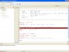
Code:
// 18F1320@ 8MHz - they are just used here for clarity...
Device = 18F1320
Clock = 8

Include "ISRTimer.bas"          

// constant ID to 4 * 16 bit timers...
Const
   Timer1 = 0,
   Timer2 = 1,
   Timer3 = 2,
   Timer4 = 3
      
// OnTimer1 event...
Event OnTimer1()
   Toggle(PORTB.0)//pin 8
End Event
Event OnTimer2()
   Toggle(PORTB.1)//pin 9
End Event


// activate the timer module...
Timer.Initialize

// initialise the timers - refresh every 1000Hz (1ms)...
Timer.Items(Timer1).Interval = 50        // 50ms
Timer.Items(Timer1).OnTimer = OnTimer1   // timer event handler
Timer.Items(Timer2).Interval = 5        // 50ms
Timer.Items(Timer2).OnTimer = OnTimer2 
  // timer event handler
Timer.Items(Timer4).Interval = 200      // 2000ms, no event handler

// enable the timers...
Timer.Items(Timer1).Enabled = true
Timer.Items(Timer2).Enabled = true
Timer.Items(Timer4).Enabled = true

// start processing all timers...
Timer.Start

// main program loop...
While true
   // this is a polled timer, not event driven - check to see
   // if it has timeout...
   If Not Timer.Items(Timer4).Enabled Then
      Toggle(PORTB.0)//pin 8
      Toggle(PORTB.1)//pin 9
      Timer.Items(Timer4).Enabled = true
   EndIf
   Toggle(PORTB.1)//pin 8   
 
Wend
 
event handler has lots to do w/ this code

I prg the PIC w/ orginal code that be80be posted, changed the B7 to 5ms
no short bursts of LEDs so shortning the ONTIME values affects everything?
pin 8 = 10-15 seconds on
pin 9 = 60 seconds on
pin 17 = 2 minutes on
timer 4 =2000 havn't figured out this on as no LED (port) to connect to.
Code:
}
// 18F1320@ 8MHz - they are just used here for clarity...
Device = 18F1320
Clock = 8

Include "ISRTimer.bas"          

// constant ID to 4 * 16 bit timers...
Const
   Timer1 = 0,
   Timer2 = 1,
   Timer3 = 2,
   Timer4 = 3
      
// OnTimer1 event...
Event OnTimer1()
   Toggle(PORTB.0)//pin 8
End Event

// OnTimer2 event...
Event OnTimer2()
   Toggle(PORTB.1)//pin9
End Event

// OnTimer3 event...
Event OnTimer3()
   Toggle(PORTB.2)//pin 17
End Event

// activate the timer module...
Timer.Initialize

// initialise the timers - refresh every 1000Hz (1ms)...
Timer.Items(Timer1).Interval = 50        // 50ms
Timer.Items(Timer1).OnTimer = OnTimer1   // timer event handler
Timer.Items(Timer2).Interval = 250       // 250ms
Timer.Items(Timer2).OnTimer = OnTimer2   // timer event handler
Timer.Items(Timer3).Interval = 500       // 500ms
Timer.Items(Timer3).OnTimer = OnTimer3   // timer event handler
Timer.Items(Timer4).Interval = 2000      // 2000ms, no event handler

// enable the timers...
Timer.Items(Timer1).Enabled = true
Timer.Items(Timer2).Enabled = true
Timer.Items(Timer3).Enabled = true
Timer.Items(Timer4).Enabled = true

// start processing all timers...
Timer.Start

// main program loop...
While true
   // this is a polled timer, not event driven - check to see
   // if it has timeout...
   If Not Timer.Items(Timer4).Enabled Then
      Toggle(PORTB.3)
      Timer.Items(Timer4).Enabled = true
   EndIf
      
   // background flash LED...
   High(PORTB.7)//pin 13
   DelayMS(5)
   Low(PORTB.7)//pin 13
   DelayMS(5)
Wend
boy this is kinda fun doing detective work on a PIC code.
I just need to learn more syntax and how to code properly.
lots of thanks to all that have submitted suggestions on this long post but there is lots of knowledge in it.
 
I think I figured it out

ONTIMER# is basically the same as DELAYMS(#) but is more reliable and accurate??
been changing vlues etc. Lots of fun discovering what a slight change can do.
going to try and eliminate all the timers except #1 and 4
apperaently #4 has something to do with event handler??
 
apperaently #4 has something to do with event handler??
this is a polled timer, not event driven - check to see
// if it has timeout...
Timer.Items(Timer4).Interval = 2000 // 2000ms, no event handler
 
Last edited:
timer 4 goes for a long time

I inserted a TOGGLE portb.3 then DELAYMS(2) then TOGGLE portB3 again.
the LED flashes brieftly when timer4 gets going
I wanted to see when it started and stoped.
and yes I get 15-18 minutes when timer4 is set for 2000
now I am trying to mix the random sound code with the timer code but I get the error can't load timermoduel4 bas file.
I put the INCLUDE just like the timer code did.
file name to long or ??
see my junebug/icd
I posted all the code from both programs.
 
conditional program jump?

problem = disable the PIR durring daylight and enable the timer
plan is if doable = have the timer and PIR routines alternate due to the state of RB#(a phototransistor to change the state of this pin thus implementing a program jump (daylight = disable the PIR routine
night time = disable the timer routine
my problem is trying to write a short routine to make the jump.
my thoughts are an IF THEN statement or a WHILE TRUE
not sure how to go about it.
trying to use Junebug to test but that charliexplexing throws a towel in the mix.
any suggestions
 
trying to code a routine skip?

I am trying to dechipfer how to do a "conditional" routine on the Junebug where I flash LEDs but when the button B0 is pressed then change the flash rate.
end result is to insert into my CRITTER RIDDER code so durring daylight the timer is enabled and the PIR is disabled(a photo transistor to take another port LOW thus disabliing the PIR and enablining the timer
code I am playing with is for the Junebug just to try out.
Code:
Device = 18f1320
Clock = 8
Config OSC = INTIO2, WDT = OFF, LVP = OFF
OSCCON = $62
TRISA=%10111110         //A0 & 6 output
PORTA=1
porta.6=0
portb.0=1
while(true)
if portb.0=0 //press button same as phototrans going low
   
   then
   porta.0=0
   delayms(60)
   porta.6=0
   delayms(60) 
    
    //if portb.0=0 then false
    //if not portb.0=0 then
  
    endif
If portb.0 = 1 then

endif
Toggle(PORTA.0)
delayms(20)
 toggle(porta.6)
 delayms(200)

    //Toggle(PORTA.6)
      //  delayms=(200)
        //Toggle(PORTA.6)   
       // delayms=(400)                              //
                         //
wend                   
   
     end
code dosn't work. it skips directly to last code routine instead of running the first routine instead.
I am missing something??
 
You want some thing like this
Code:
If portB.0 =0 then
 Led0 =1
elseif portB =1 then
 Led0 = 0
Endif
just use your ports for Led0 and the portX
 
Mr deb take a look at this I no it's not what you want but your code will not run it's missing a lot to make it work this show you how to set the ports so you can read the switches
Code:
Device = 18f1320
Clock = 8
Config OSC = INTIO2, WDT = OFF, LVP = OFF
Include "Utils.bas"
OSCCON = $72
SetAllDigital      //set digital so you can read RB0 or it will always read low
INTCON2.7=0        // sets wpu on portb
TRISB =%11111111  // sets all portb to input
PORTB =%00000000  // set it low 
TRISA =%00000000   // sets porta to output
PORTA =%00000000   //sets it low                       

While(true)
    If (PORTB.0 =0)  Then     //test to see if it gos low sw1
    PORTA.0 = 1               //if low led1 and 6 will light
    DelayMS(20)               // debounce delay
    ElseIf (PORTB.0 =1) Then   // test if high 
    PORTA.0 = 0                // if high leds will be out
    EndIf
Wend                   
   
     End
 
Last edited:
This is what you posted before

to read the switches etc.
and I am pretty sure it works?
Code:
Device = 18F1320
Clock = 8 // 8MHz clock
Config OSC = INTIO2, WDT = OFF, LVP = OFF
Include "timer module 4.bas"

Dim NOT_RBPU As INTCON2.7
Dim TMR1IE As PIE1.0
Dim TMR1IF As PIR1.0
Dim TMR1 As TMR1L.AsWord
Dim Speaker As PORTB.3
Dim SpeakerTris As TRISB.3

Dim Amp As PORTB.1 // turns on amp power
Dim AmpTris As TRISB.1//turns on amp pin 9
Dim Speed As Word
Dim dip1 As PORTA.0

Dim dip2 As PORTA.1

Dim dip3 As PORTA.2

Dim dip4 As PORTA.3

Dim dipRD As PORTB.0

//global variables
Dim Seed As LongWord, Tone As Byte
Dim i As Byte

//half period delays = clock speed divided by 2*frequency
Const Tones(18) As Word = (2000000/12000,2000000/10000,2000000/8000,2000000/6000,2000000/4000,1000,
2000000/12000,2000000/10000,2000000/8000,2000000/6000,2000000/4000,1000,2000000/12000,2000000/10000,2000000/8000,2000000/6000,2000000/4000,1000)

//interrupt routine
Interrupt MyInt()
          T1CON.0=0 //stop timer
          TMR1=-Tones(Tone) //reset period
          T1CON.0=1 //restart timer
If Tone=5 Then //if silence
   Speaker=0 //speaker off
Else //otherwise
Toggle(Speaker) //make sound

EndIf
TMR1IF=0 //clear interrupt flag
End Interrupt

Function Rand(Range As Byte) As Byte
Dim i As Byte, feed As Bit, temp As Word
For i = 0 To 7 //generate 8 bits
    Feed = Seed.30 Xor Seed.27 //make new bit
    Seed=Seed*2+Feed //shift seed left and add new bit
Next
    Temp=(Seed And 255) * Range //change Rand from 0 to 255
    Rand = Temp/256 //to 0 to (Range-1)
End Function

//main code starts here


//main code starts here

       OSCCON = $72            //select 8MHz internal clock
       NOT_RBPU=0              //WPUs on port B
       ADCON1=$7f              //all digital
       TRISB.0=0               //make output
       PORTB.0=1 //makes pin 8 high for dip switches
       T1CON = %10000001       //pre=1
       T1CON = %10000001 //pre=1
       Tone=5 //no sound please
       TMR1IE=1 //enable timer 1 interrupt
Enable(MyInt) //set interrupt going
SpeakerTris=0 //Setup Port
Seed=$12345678 //seed random number
        TRISA =%00001111          //sets your inputs on porta 
While(TRUE) //repeat forever

    If dip1=1 Then //dip1 pin 1
       Speed=25
    EndIf
    
    If dip2=1 Then // dip 2 pin 2
       Speed=50 
    EndIf
    
    If dip3=1 Then //dip3 pin 6
       Speed=75
    EndIf
    
    If dip4=1 Then //dip4 pin 
       Speed=Rand(10)*15+15    //Speed = 25 to 250 random select speed
       
    EndIf
PORTA.0=1  
If PORTB.1=0 Then //if button 1 pressed add PIR=1 here pin 9
For i = 1 To 200 //play 20 tones
    Tone=Rand(5) //each tone is random frequency
DelayMS(Speed) //and for 1.00 seconds
Next //end for loop
Else //otherwise
     Tone=5 //silence
     i=Rand(255) //make rand more random
      PORTA.0=0
EndIf //end if condition
Wend //end of while loop

Ineed to add the timer module and the PIR disable code that you just posted
I hope this is all of it??
 
disable routine dosn't work??

I get and END EXPECTED error
Code:
Device = 18f1320
Clock = 8
Config OSC = INTIO2, WDT = OFF, LVP = OFF

TRISA=%10111110         //A0 & 6 output
dim but as portb.0
dim butTRIS as TRISB.0 
end if

If portB.0 =0 then
 porta.0 =0
elseif portB =1 then
 
PORTA=1


end if
end
I added the ports A0 = first led
A6 = second led
B0 = button.
I entered the code exactly as you posted =no worky
I added the input B0 (I think by putting the trisa??)
 
This "end if" looks out of place
Code:
Device = 18f1320
Clock = 8
Config OSC = INTIO2, WDT = OFF, LVP = OFF

TRISA=%10111110         //A0 & 6 output
dim but as portb.0
dim butTRIS as TRISB.0 
[B]end if[/B]

If portB.0 =0 then
 porta.0 =0
elseif portB =1 then
  PORTA=1
end if

end
 
That's because
Code:
 Endif       // is right
End if      //is wrong
Code:
 Device = 18f1320
Clock = 8
Config OSC = INTIO2, WDT = OFF, LVP = OFF

TRISA=%10111110         //A0 & 6 output
dim but as portb.0
dim butTRIS as TRISB.0 
[COLOR="Red"]end if   // don't need this will not work[/COLOR]

If portB.0 =0 then
 porta.0 =0
elseif portB =1 then
  PORTA=1
[COLOR="Red"]end if // this should be endif not end if[/COLOR]

end
 
Last edited:
no worky guys??

get END EXPECTED error
 

Attachments

  • Capture6-12-2009-4.01.24 AM.jpg
    Capture6-12-2009-4.01.24 AM.jpg
    149.9 KB · Views: 282
lol why is the First END there? remove it completely
This looks more of what you are trying to do :D
Code:
Device = 18f1320
Clock = 8
Config OSC = INTIO2, WDT = OFF, LVP = OFF

dim but as portb.0      //Define but as PORTB bit 0
dim butTRIS as TRISB.0  //Define butTRIS as TRISB Bit 0

OSCCON = $72            // 8 MHz clock

TRISA=%10111110         //A0 & 6 output
butTRIS = 1             //Set Button as Input

If but = 0 then         //If but is 0 then 
    porta.0 =0          //PORTA Bit 0 = 0
elseif but = 1 then     //Else if but = 1 then
    porta.0=1           //PORTA Bit 0 = 1
endif                   //end of if statement

NOTE: I dont have Swordfish installed so cant test it :(
 
Last edited:
NO it don't work?

haven't a clue why as I am using the Junebug to test.
maybe the charlieplexing is messing the code up??
 
heres a thought = pullup resistors

there are no pullup resistors on the pushbuttons on the junebug.
this could be the problem??
 
there are no pullup resistors on the pushbuttons on the junebug.
this could be the problem??
I posted you code that fixed that problem
Code:
SetAllDigital      //set digital so you can read RB0 or it will always read low
INTCON2.7=0        // sets wpu on portb
 
You need to set your ports like this
Code:
Device = 18f1320
Clock = 8
Config OSC = INTIO2, WDT = OFF, LVP = OFF
include "Utils.bas"
Dim but AS PORTB.0
Dim led AS PORTA.0
SetAllDigital      //set digital so you can read RB0 or it will always read low
TRISA =%00000000  // if your using the junebug This is fool proof to get a led to lite
PORTA =%00000000  // Set's it all low
TRISB =%00000001  // Set's inputs and outputs 
PORTB =%00000000   // Set's it all low
INTCON2.7=0        // sets wpu on portb turns on pullups on PORTB
OSCCON = $72            // 8 MHz clock
while true              // this loops it so it keeps checking 
IF but = 0 then        // checks button 1 on the junebug to see if low
    led =0                 // Turns off led
    delayMS(10)       // small debounce delay
elseif but = 1 then  // checks button 1 on the junebug to see if high
   led =1                 // Turns on led
   delayMS(10)       // small debounce delay
endif                     // closes your IF THEN statements 
wend

END
 
Last edited:
Status
Not open for further replies.

New Articles From Microcontroller Tips

Back
Top