Hello people!
I am working on a radio controlled motor application. I constructed the circuits mostly based on Nigel Goodwin's PIC tutorials. Actually, the code is also basically from those tutorials. I just combined, copied, pasted some code with another. These are , PWM, Manchester encoding, Joystick reading and delay code parts. So i haven't written any of this routines. As i said i just combined parts that i need in order to meet my needs.
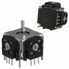
To test the Analog Joystick reading part (Tutorial 4) i connected joystick to PIC16F628 (PIC that i used) and PIC to motor driver (L293D), and a DC motor to it. The overall schematic should be included in the attachment. For a start i tried to read only X axis of analog joystick. So as a result, i wanted to get the motor roll forward and reverse according to X axis position. Also, i am using mini analog joystick, rather than PC analog joystick. The picture should also be included in the attachment.
So the problem is, it doesn't work. As soon as i turn the power on, the motor starts to turn. That's all. Please, help to figure out whats wrong. It should be in the code, that i have messed up.
This is the code:
I am working on a radio controlled motor application. I constructed the circuits mostly based on Nigel Goodwin's PIC tutorials. Actually, the code is also basically from those tutorials. I just combined, copied, pasted some code with another. These are , PWM, Manchester encoding, Joystick reading and delay code parts. So i haven't written any of this routines. As i said i just combined parts that i need in order to meet my needs.
To test the Analog Joystick reading part (Tutorial 4) i connected joystick to PIC16F628 (PIC that i used) and PIC to motor driver (L293D), and a DC motor to it. The overall schematic should be included in the attachment. For a start i tried to read only X axis of analog joystick. So as a result, i wanted to get the motor roll forward and reverse according to X axis position. Also, i am using mini analog joystick, rather than PC analog joystick. The picture should also be included in the attachment.
So the problem is, it doesn't work. As soon as i turn the power on, the motor starts to turn. That's all. Please, help to figure out whats wrong. It should be in the code, that i have messed up.
This is the code:
Code:
  LIST    p=16F628        ;tell assembler what chip we are using
    include "P16F628.inc"        ;include the defaults for the chip
    ERRORLEVEL    0,    -302    ;suppress bank selection messages
    __config 0x3D18            ;sets the configuration settings (oscillator type etc.)

    cblock     0x20             ;start of general purpose registers

        count            ;used in looping routines
        count1            ;used in delay routine
        count2
        counta            ;used in delay routine
        countb            ;used in delay routine
        temp
        tmp1            ;temporary storage
        tmp2

           HiX            ;result for X pot
        LoX
        HiY            ;result for Y pot
        LoY
        Flags

    endc

JOY_PORT    Equ    PORTA
JOY_TRIS    Equ    TRISA
PotX        Equ    0x06            ;input assignments for joystick
PotY        Equ    0x02
MR    Equ    0x04    ;pin for motor reverse
MF    Equ    0x05    ;pin for motor forward
;pin 3 (RB3) is the PWM channel output -CCP1

        org    0x0000
        nop
        nop
        nop
        goto    Start
        org 0x0010

Start        movlw    0x07
        movwf    CMCON            ;turn comparators off (make it like a 16F84)

Initialise    clrf    count
        clrf    PORTA
        clrf    PORTB

SetPorts    bsf     STATUS,        RP0    ;select bank 1
        movlw    0xff            ;make all joystick pins inputs
        movwf    JOY_TRIS
        bcf     STATUS,        RP0    ;select bank 0

        call    JOY_Init        ;discharge timing capacitors
        call    PWM_Init        ;

Main
        call    ReadX            ;read X joystick
    ;    call    ReadY            ;read Y joystick

        MOVLW    LoX
        CALL    SpeedL        ;half speed forwards


        goto    Main            ;loop for ever

;joystick routines

JOY_Init                ;setup joystick port
    bsf     STATUS,        RP0    ;select bank 1
    bcf    JOY_TRIS,    PotX    ;make PotX an output
    bcf    JOY_PORT,    PotX    ;discharge capacitor
    bcf    JOY_TRIS,    PotY    ;make PotY an output
    bcf    JOY_PORT,    PotY    ;discharge capacitor
    bcf     STATUS,        RP0    ;select bank 0
    retlw    0x00

ReadX
    clrf    HiX            ;reset counter registers
    clrf    LoX
    bsf     STATUS,        RP0    ;select bank 1
    bsf    JOY_TRIS,    PotX    ;make PotX an input
    bcf     STATUS,        RP0    ;select bank 0

x1
    btfsc    JOY_PORT,    PotX    ;keep going until input high
    goto    EndX
    incfsz    LoX,f
    goto    x1
    incfsz    HiX,f
    goto    x1

EndX    bsf     STATUS,        RP0    ;select bank 1
    bcf    JOY_TRIS,    PotX    ;make PotX an output
    bcf    JOY_PORT,    PotX    ;discharge capacitor
    bcf     STATUS,        RP0    ;select bank 0
    retlw    0x00

ReadY
    clrf    HiY            ;reset counter registers
    clrf    LoY
    call    Delay5
    bsf     STATUS,        RP0    ;select bank 1
    bsf    JOY_TRIS,    PotY    ;make PotY an input
    bcf     STATUS,        RP0    ;select bank 0

y1
    btfsc    JOY_PORT,    PotY    ;keep going until input high
    goto    EndY
    incfsz    LoY,f
    goto    y1
    incfsz    HiY,f
    goto    y1

EndY    bsf     STATUS,        RP0    ;select bank 1
    bcf    JOY_TRIS,    PotY    ;make PotY an output
    bcf    JOY_PORT,    PotY    ;discharge capacitor
    bcf     STATUS,        RP0    ;select bank 0
    retlw    0x00

;PWM routines
PWM_Init:
        BANKSEL  PORTB
        BANKSEL  TRISB
        MOVLW    3        ;set PORTB as all outputs
        MOVWF    TRISB
        BANKSEL  PORTB

        MOVF     CCP1CON,W    ;set CCP1 as PWM
        ANDLW    0xF0
        IORLW    0x0C
        MOVWF    CCP1CON

        MOVLW    126        ;set highest PWM value
        BANKSEL  PR2        ;over this (127) is permanently on
        MOVWF    PR2
        BANKSEL  TMR2

        MOVF     T2CON,W    ;set prescaler to 16
        ANDLW    0xF8        ;PWM at 2500HZ
        IORLW    0x02
        MOVWF    T2CON

        MOVF     T2CON,W    ;set postscaler to 1
        ANDLW    0x07
        IORLW    0x00
        MOVWF    T2CON

        CLRF    CCPR1L        ;set PWM to zero

        BSF      T2CON, TMR2ON    ;and start the timer running
    RETURN

SpeedL:                ;use value in W to set speed (0-127)
        MOVWF    temp
        BTFSC    temp, 7        ;if more than 128 set speed in reverse
        CALL    ReverseL    ;so '1' is very slow forward
         BTFSS    temp, 7        ;and '129' is very slow reverse
        CALL    ForwardL
        ANDLW    0x7F
        MOVWF   CCPR1L
    RETURN

ReverseL:
    BSF    PORTB, MR    ;set pins for reverse
    BCF    PORTB, MF
    RETURN

ForwardL:
    BCF    PORTB, MR    ;set pins for forward
    BSF    PORTB, MF
    RETURN

;Delay routines

Delay255    movlw    0xff        ;delay 255 mS
        goto    d0
Delay100    movlw    d'100'        ;delay 100mS
        goto    d0
Delay50        movlw    d'50'        ;delay 50mS
        goto    d0
Delay20        movlw    d'20'        ;delay 20mS
        goto    d0
Delay5        movlw    0x05        ;delay 5.000 ms (4 MHz clock)
d0        movwf    count1
d1        movlw    0xC7            ;delay 1mS
        movwf    counta
        movlw    0x01
        movwf    countb
Delay_0
        decfsz    counta, f
        goto    $+2
        decfsz    countb, f
        goto    Delay_0

        decfsz    count1    ,f
        goto    d1
        retlw    0x00

;end of Delay routines

        end