Continue to Site

Welcome to our site!

Electro Tech is an online community (with over 170,000 members) who enjoy talking about and building electronic circuits, projects and gadgets. To participate you need to register. Registration is free. Click here to register now.

  • Welcome to our site! Electro Tech is an online community (with over 170,000 members) who enjoy talking about and building electronic circuits, projects and gadgets. To participate you need to register. Registration is free. Click here to register now.

JK latch, 12V

Status
Not open for further replies.

Wylliam

New Member
Hi,
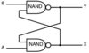
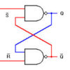
I need to build a circuit with a simple JK latch where Set, Reset and Output signals all are 12V (see picture). Max current on the output should be about 150mA.
Is it possible to use a CMOS flipflop (CD4027) or shall I rather go for a double winding latching relay (larger and more expensive)?
Thanks in advance for your help!
Wylliam
 

Attachments

  • JK-latch.jpg
    JK-latch.jpg
    42.1 KB · Views: 215
You will be hard pressed for the 150mA. May I ask exactly what you are wanting to do? Since you mention a latching relay and if you want a latching circuit then a D flip flop like the CD4013 might be a better choice or any D flip flop type IC. Push a single button once and things turn on, push the same button again and things turn off.

Ron
 
Any CD4000 series FF will work if you are just using the Set/Reset inputs. You need a resistor to ground on both the inputs so the input is logic low when the switches are open (and all unused inputs must be grounded).

You can get 150mA by using a MOSFET buffer on the FF output.
 
Last edited:
Here is the story from the beginning:
I have a position switch that will detect when an object enters a given area. When the switch closes it should activate a GSM-dialer that sends an SMS warning that the object has entered the critical area. The problem is that the object moves very slowly and even if the position switch won't snap at the exact same position when opening or closing I am concerned that the input signal to the dialer will alternate (because of vibrations) thus sending more than one SMS. So I was looking for a way to "remember" the first up front of the raw signal until the system is manually reset.
My first idea was to use a double winding latching relay but they are relatively expensive and quite bulky. So I would prefer a solution with a cheaper and more compact IC.
The output current 150mA is likely to be overdriven. I could not find any information about the resistance of the dialer input. But the wiring can be done as on the attached figure. From that I guess that the input resistance is well over 1kOhm and the current should thus be below 10mA (What do you think?)
The LEDs are going to lower the tension a little bit. Do you think it still can be considered as 12V? (not exactly but within tolerances)
Thanks a lot!
Wylliam
 

Attachments

  • Dialer_input.jpg
    Dialer_input.jpg
    12.1 KB · Views: 176
Here's a latch circuit using just two inverters. The resistors in the cross-coupled connections substitute for the pull-down resistors normally required for the switches. The inverter can be a CD4049.

An interesting characteristic of this circuit is that it will also work if you connect the switches to ground instead of 12V. Of course, that reverses the polarity, so the Set becomes the Reset and vice versa.


Latch.gif
 
Crutschow, your set switch is shown in the active position. In this setup, the output will only go low when the reset switch is active, and will immediately go back set when the reset switch is released. both input switches should be in the NO position when not actively being pressed.
 
Crutschow, your set switch is shown in the active position. In this setup, the output will only go low when the reset switch is active, and will immediately go back set when the reset switch is released. both input switches should be in the NO position when not actively being pressed.
That's true. I should have made that clear. The indicator shows the state of the latch (red is logic high) immediately after the Set switch is closed (and released).
 
Status
Not open for further replies.

Latest threads

New Articles From Microcontroller Tips

Back
Top